Lift Top Coffee Table Project Plan
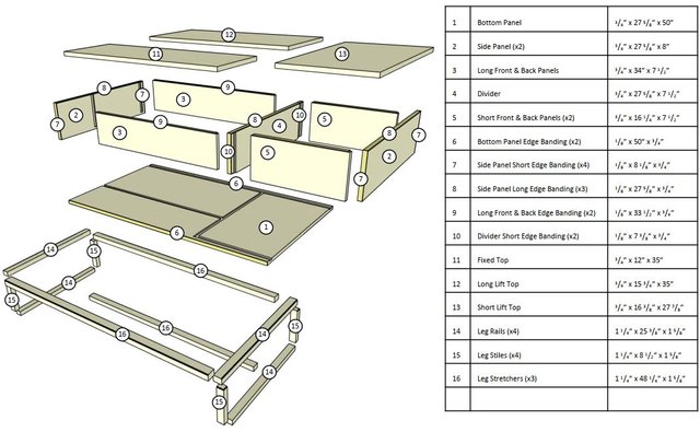
Parts and Materials:
Introduction:
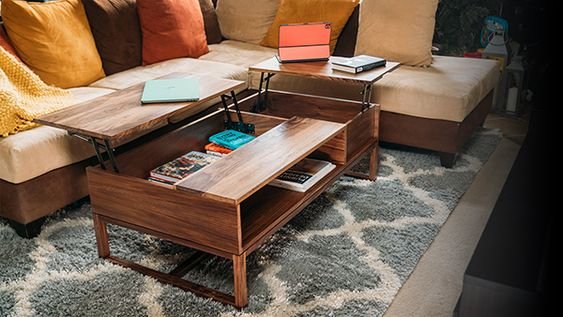
My wife and I love watching movies and TV together on the couch. So it’s no surprise we get a lot of use out of our living room. But that also means we like eating
our meals in front of the TV and doing computer work on the couch as well. A lift-top coffee table would be the perfect addition to our home. Now we can eat in front of
the TV by lifting the coffee table top to just the right height. No more sitting awkwardly on the floor and risk spilling drinks. The lift top also makes it more
convenient to do work on the couch, while having the TV on. This coffee table features two lift tops, perfect for multiple members of the family, and a great fit for
living rooms with sectionals.
Making the case:
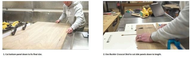
The case is made from 3/4” walnut plywood, with 1/8” hardwood edgebanding. I will start by breaking down the plywood for the bottom and two side panels to their
final sizes. And I will cut the rest of the pieces slightly oversized for easier handling.
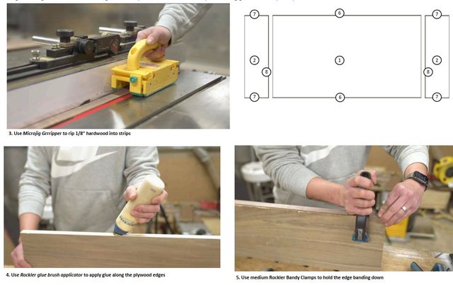
Then I will rip 1/8” pieces of hardwood to slightly more than 3/4” wide for edge banding. The strips will be cut longer than the length of the panels as well. I’ll
flush up the strips to the panels later. The bottom panel will receive two pieces of edgebanding along the long edges, and the two side panels will both receive
edge banding on three of the four edges. The strips will be attached to the panels using glue and bandy clamps.
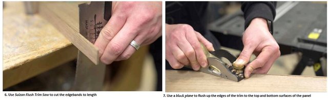
Once the glue has cured, I used a flush trim saw and a block plane to flush the edgebanding to the panels.
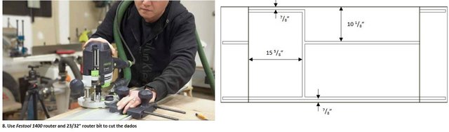
After the edgebanding is flushed up, it’s time to cut the joinery. I used a 23/32” plywood router bit in my router to cut the dados. I pushed the two side panels
against the bottom panel with their edges flush against each other. Then made the cuts with a single pass. This ensures the dados will line up.
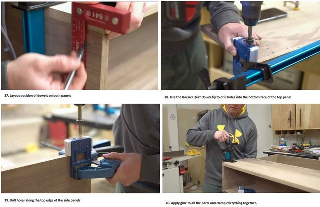
Next, I’m going to prepare for assembling the three sides of the case. I will be using dowels to add strength and help with alignment. First, I will place the side
panels on the correct side of the bottom panel, then make sure the edges are flush against each other and clamp them down. This will ensure the panels will not
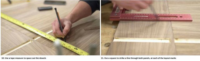
move as I begin laying down the locations of the dowels. I will place the first dowel about 3/4” from the edge of the dado, and then the rest will be spaced roughly
3” apart. Once I’ve made the marks, I will use a square to strike a line through both panels at each of the marks. This will help to ensure the layout lines will line up
perfectly between both panels.
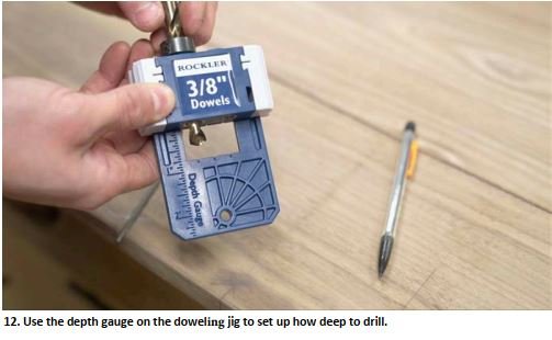
Now, it’s time to set up the Rockler Doweling Jig. Since I am building the case out of 3/4” panels, I will use 3/8” dowels for this. The jig has a depth gauge
engraved in the back to help me quickly set up the drill bit. Since the dowels are 1” long, I set up the depth to 1/2”, and then tightened the stop collar.
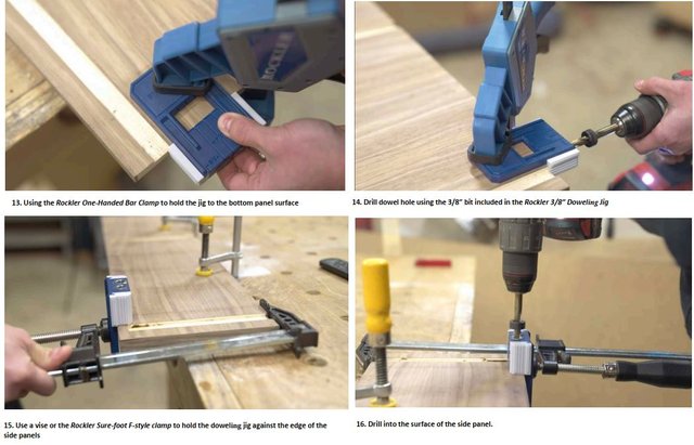
Now just line up one of the reference marks on the jig to one of the layout lines we made to start drilling. It is straightforward for the bottom panel since the
dowel holes will be drilled along the edge, the reference surface will be the top surface. But since we’ll be drilling into the top surface of the side panels, the
reference surface will have to be the edge. So a longer clamp will be needed to clamp the jig to the workpiece. This is where a vise will come in handy if you have
one.
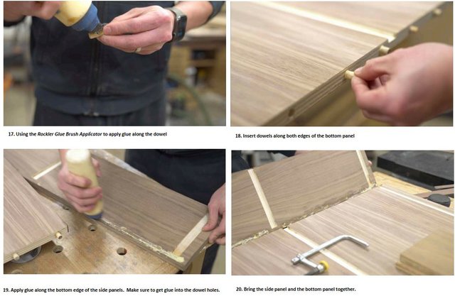
Once all the dowel holes are drilled, it’s time to insert the dowels. I’ll start by applying a bead of glue along the dowel and inserting them into the holes along both
edges of the bottom panel. Then apply glue along the bottom edges of both side panels and make sure to get some glue into the dowel holes as well. Then just
bring the side panels and the bottom panel together. As long as you’ve taken the time to layout the reference lines previously, these panels should come together
with ease.
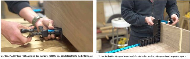
Then clamp the case together using clamps. Since only three panels are being glued together in this step, it’s important to use clamping squares to ensure
everything is at 90º as the glue cures.
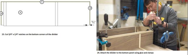
After the glue has had some time to cure, I came back to cut the divider to size and cut the dados into the panel to match those on the bottom panel. I cut 3/4” x
1/4” notches on the bottom corners of the divider to allow the front and back edges to sit flush to the bottom panel edges. If you prefer the look of dados, feel free
to cut the dado all the way through on the bottom panel. Then, just apply glue in the dado of the bottom panel and attach the divider. Once again, I used clamping
squares to help ensure the piece is 90-degrees. I also used a long piece of offcut as a caul to help with spreading out the clamping pressure along with the entire piece
since I cannot get clamps to the middle of the panel.
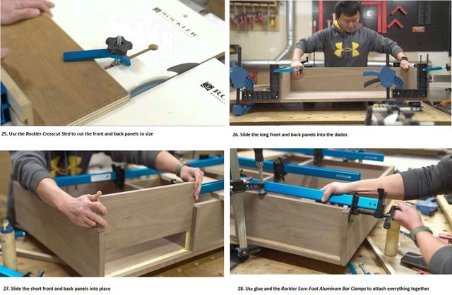
With the sides and the divider glued in place, I can measure between the dados and cut the front and back pieces to size. Then, just slide the pieces into the dados,
apply glue, and clamp them up.
Making The Top:
The top will consist of three separate panels made from 4/4 walnut hardwood. I chose not to use plywood for the top because the top will likely be used a lot, so I
want it to be able to stand up to some level of abuse. I will also cut finger grooves to the bottom to help with holding the top when opening it, and I don’t want the
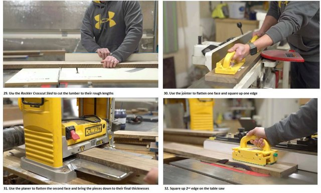
plywood edges to show. To begin making the top panels, I will first cut the 4/4 lumber down to their rough lengths to make it easier to handle. Then I will run them
through the jointer to flatten one face and square up to one edge. Next, I’ll run them through the planer to flatten the second face and bring the pieces down to their
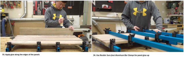
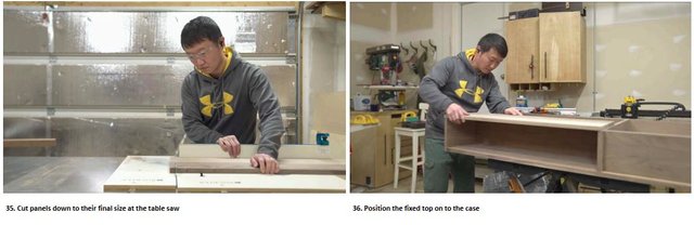
final thicknesses. Finally, I’ll run them through the table saw to square up the second edge, before gluing them up to form larger panels.
After leaving the pieces glued up for a few hours, I came back later that day to cut them down to their final sizes. Then, I can attach them to the case. I started with
the fixed top panel, which will be attached using dowels and glue. I placed it on top of the case, making sure all the sides are flush, and then clamped it down. Then I
used a square to mark the locations of the dowels and drilled the holes.
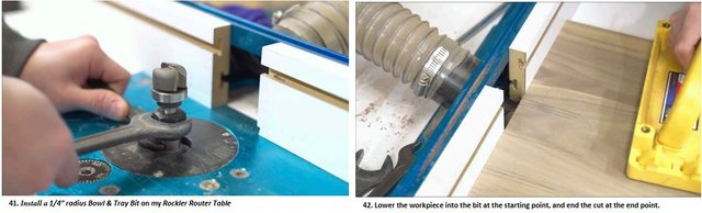
Before attaching the two lift tops, I decided to use a 1/4” diameter bowl & tray bit in my router table to cut the finger grooves. I drew lines on the board to indicate
the start and stop locations of the cut. After lining up the starting line, I’ll slowly lower the panel down into the bit, making sure to apply pressure into the fence, and
downward into the table to avoid kickback. I find that lowering the panel down into the bit was less likely for me to get a kickback compared to just pushing the panel
into the bit.
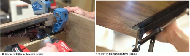
Once the handles were cut, attaching it to the lift top mechanism was pretty straightforward, although not very easy to get it perfect. I used a piece of offcut as a
spacer to help me place the mechanism so that its top surface was flush to the top edge of the case. I clamped it in place and secured it to the case using 3/4”
screws. To secure the top panels to the mechanism, I had to measure the locations of one of the holes on each bracket, then transfer those measurements to the top
panel. Then secure the rest of the screws. Every lift top mechanism will be different, so follow the supplier’s instructions for this.
Making The Legs
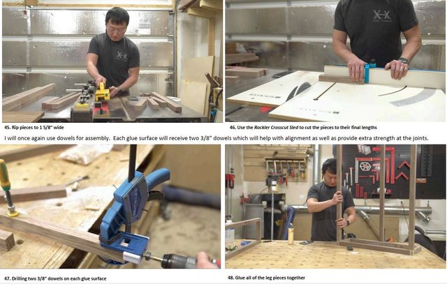
The legs will consist of two rectangular assemblies, attached with three stretchers, all made from 8/4 solid walnut. Following the same process as that for the top
panels, I milled the pieces to 1 1/4” thick, then ripped them to 1 5/8” wide, before finally cutting them to their final lengths.
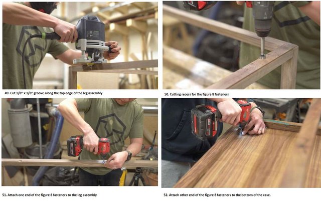
After allowing the glue to cure for a day, I came back the next day and used a rabbeting bit in my router to cut a 1/8” x 1/8” groove along the top edge of the legs.
This is a choice I made to give separation between the legs and the case. This gives it a more modern aesthetic. After cutting the groove, I will use a 3/4” Forstner bit
to drill a few recesses for receiving the Figure 8 Fasteners that I will use to attach the leg assembly to the case.