Single Phase Electricity Meter | System installation and promotion
What is the project about?
The purpose of this work is to design a digital active single-phase power meter using the 18 series PIC microcontroller.
In this study 18F4620 was used as 18 series PIC. The software is in CCS C language.
The software also includes a day-to-day development of a single-phase digital active electricity meter and an example of a single-phase digital active electricity meter.
Technology Stack
- PIC C Compiler
- 20ms of sinus wave
- It is written with proper codes by taking 200 samples in 2ms intervals.
- Current information is shown with LCD.
Roadmap
- Introducing the system.
- Installing the system.
- Tell what the system is.
- Write codes with CCS C pic programming.
- Making the system work.
How to contribute?
- Report a bug,
- Send pull request,
- Send mail to me be a contributor.
- Feel free to ask anything, any language.
Single Phase Electricity Meter
Electricity meters are needed in homes, workshops, factories, in short, wherever power is wasted. The wasted power is a visual representation. Mechanical and electronic counters are divided into two. Mechanical meters are not used as of today.
Increasing sensitivity of the technology is increasing the usage of electronic meters.Despite the similarity of electronic meters with mechanical meters in terms of circuit connections and functions, the operating principles required for the structures are different from mechanical meters. In short, the operation of electronic meters,
the current and voltage information of the unit they are connected to can be described as the consumption information by transferring them to the LCD screen by using the electronic circuits to perceive and evaluate the information.However, unlike mechanical meters of electronic meters, it is also possible to observe the meter labels as well as the meter labels and the date, time, tariff information and number of external interventions.
General Features of the PIC18F4620 Microcontroller
The PIC 18F4620 carries the characteristics of the PIC 16F8XX family first. Harvard architecture was used in PIC 18F4620. In the Von Neuman architecture, access to the program memory and the data memory is made differently in this architecture, while the data and program memory can be accessed in the same way.
The databus is 8 bits wide. At the same time, when the data memory is accessed in this way 8 bits wide, the program memory is accessed by the program path or another 14-bit wide address path (program bus / address bus). The command codes (opcode) for PIC 16F87X and PIC 16F84 for this are 14 bits.
Each address of the 14-bit program memory corresponds to an instruction code (Instruction Code / Instruction Word). Each command is therefore accessed in a cycle and loaded into the command register. The command register is a register used by the CPU, and all commands, except branch commands, they are operated on the same cycle. Meanwhile, the program counter, PC (Program Counter) is an increment. The branching or diverting commands are executed in two consecutive cycles and the program counter PC is incremented by two.
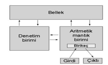
- The above figure Von Neumann architecture
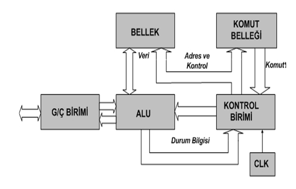
- The above figure Harvard architecture system
One of the most important subunits of the central processing unit (CPU) is the arithmetic logic unit called ALU (Arithmetic Logic Unit). The task of the ALU is to perform arithmetic or logical operations on the data sent to it. One of the ALU has two main inputs, the W (Working Register) being the name given to the register.
Two data (operators) that come to the ALU can be picked up and removed. It can do various logic operations (like, and, or, xor).
The most commonly used register in microprocessors is the "working register". This is called W for short. W executes two functions together in arithmetic and logic operations. Before the operation, it contains one of the operands.
After processing, it stores the result of the operation. In the PIC 18F4620 and 16F87X series microcontrollers, the microprocessor is reported to be held in W or other register with the number 1 or 0 placed at the end of the command (d).
Key Features of the 18FXXXX Microcontroller Family
- CPU reduced instruction set
- Uses Harvard architecture.
- Based on RISC.
- There are 75 commands to learn and each is 14 bits long.
- Branching instructions are applied in two cycles, while others are executed in one cycle.
- The processing speed is DC 40 MHz at 18F4620.
- Data bus (databus) is 8 bits.
- There are 32 special transaction registers called Special Function Registers (SFRs), which are on static RAM.
- Up to 64Kx14word flash memory can be programmed 1 million times.
- Increased data memory (RAM) up to 3968x8 Bytes,
- EEPROM data memory up to 1024 Bytes.
- Pin outputs compatible with PIC 16F877.
- Can cut from 14 sources.
- Stack depth is 8.
- Can make direct, indirect and relative addressing.
- Poweron Reset (System reset function when power is applied)
- Powerup Timer (Powerup timer)
- Oscillator Startup Timer (Oscillator start timer)
- Watchdog Timer (special type timer), in-line RC oscillator
- Ability to provide code safety with the program
- In-line Debugger (module that can be used for debugging)
- Low voltage programming
- Flash ROM program memory (EEPROM-enabled program memory)
- Energy-saving sleeping mode
- Optional oscillator features
- Parallel port control is possible.
- Low-power, high-speed, CMOSFlash EEPROM technology
- Totally static design
- 2 pin programmable feature
- 5V input only, in-line serial programming feature
- Access to the processor's program memory with read / write capability
- 2.0 V - 5.
- Wide operating range from 0 V
- 25mA welding current
- On-board, two pin debugging feature
- Ability to work in wide temperature range
- Low power operation
- Resistant to -40 ° C to 125 ° C under bias voltage
- It is between -65 ° C and 150 ° C.
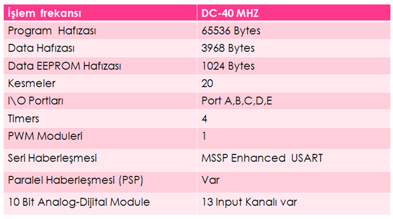
- The above figure Pic 18F4620's information
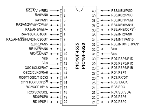
- The above figure Pic 18F4620 Leg Appearances
DS1302 Real Time Clock
DS1302; The RTC has a calendar and 31 bytes of RAM (battery protected). It communicates with the microprocessor through a simple serial interface. The real time clock (RTC) contains the day, minute, hour, day, month, year, day of the week, and date information until 2100. It can operate at voltages between 2.0 V and 5.0V. 2nd.
At 0 V, less than 300 nA of current is consumed. It has a burst or read mode for writing and reading in the clock and RAM memory. Compatible with TTL (Vcc = 5 V). - It can work between 40 ° C and + 85 ° C.
The DS1302 has two different inputs (VCC1, VCC2).
The DS1302 keeps its clock and time information in memory even when the battery is not energized by a battery connected to one of these terminals. When Vcc1 is at Vcc2 + 0.2V, the DS1302 feeds through Vcc1. Likewise, when the Vcc2 reaches Vcc1 + 0.2V or greater, the DS1302 automatically switches they start using the Vcc2 pin for supply voltage. All communications with the DS1302 begin with a command byte. The most significant bit (MSB) of the command byte must always be a logic "1".
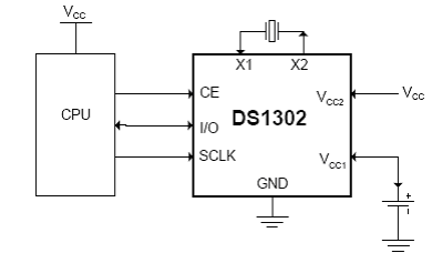
- The above figure DS1302 RTC leg connection
Voltage Transformer
- The transformer is a transformer. Figure 2. As shown in Figure 2, at least two separate coils wrapped around the same iron core (core) are formed. Wirewire primer receiving input voltage; the output voltage is called the secondary. Most of the time there are more secondary than two. The variable current ac voltage supplied to the primary creates a varying magnetic field in the iron core.
- This magnetic field, coupled to the secondary by the core, cuts off the secondary windings and induces an ac voltage across each windings. Thus, energy is transferred to the secondary from the primary by the changing magnetic field between them without any electrical connection.
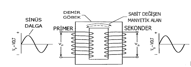
- The above figure Structure of the transformer
Current Transformer
The current transformer is a measure transformer that reduces the primary current to a secondary side within a certain ratio and the phase difference between the primary current and the secondary current is zero degrees. It provides isolation of the relays and measuring instruments from the high voltage system. The primer is connected to the serially connected coils, relay and measuring instruments.
The division of the primary circuit current into the secondary circuit current indicates the conversion factor of the current transformer. The second terminal in the current transformer connected to the system should never be open. Otherwise the current traf- fic will be damaged and undesirable situations may occur.
The secondary ends can be left in a short circuit state.
It is possible to find the current transformer as a relay mounted, busbar mounted, cable mounted and detachable body. A cable-mounted current transformer that converts 10A / 10mA is used in this project. The error margin of TEDAS is 0.5%.
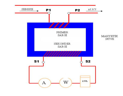
- The above figure Structure of the current transformer
.DS1302 CODES
#ifndef RTC_SCLK
#define RTC_SCLK PIN_C1
#define RTC_IO   PIN_C2
#define RTC_RST  PIN_C0
#endif
void write_ds1302_byte(BYTE cmd)
{
   BYTE i;
   for(i=0;i<=7;++i)
{
      output_bit(RTC_IO, shift_right(&cmd,1,0) );
      output_high(RTC_SCLK);
      output_low(RTC_SCLK);
   }
}


void write_ds1302(BYTE cmd, BYTE data)
 {
   output_high(RTC_RST);
   write_ds1302_byte(cmd);
   write_ds1302_byte(data);
   output_low(RTC_RST);
}

BYTE read_ds1302(BYTE cmd)
{
   BYTE i,data;
   output_high(RTC_RST);
   write_ds1302_byte(cmd);

   for(i=0;i<=7;++i)
{
      shift_right(&data,1,input(RTC_IO));
      output_high(RTC_SCLK);
      delay_us(2);
      output_low(RTC_SCLK);
      delay_us(2);
   }
   output_low(RTC_RST);
   return(data);
}

void rtc_init()
{
   BYTE x;
   output_low(RTC_RST);
   delay_us(2);
   output_low(RTC_SCLK);
   write_ds1302(0x8e,0);
   write_ds1302(0x90,0xa4);
   x=read_ds1302(0x81);
   if((x & 0x80)!=0)
     write_ds1302(0x80,0);
}

int get_bcd(BYTE data)
{
   int nibh;
   int nibl;
   nibh=data/10;
   nibl=data-(nibh*10);
   return((nibh<<4)|nibl);
}

int rm_bcd(BYTE data)
{
   int i;
   i=data;
   data=(i>>4)*10;
   data=data+(i<<4>>4);
   return data;
}

void rtc_set_datetime(BYTE day, BYTE mth, BYTE year, BYTE dow, BYTE hr, BYTE min)
{
   write_ds1302(0x86,get_bcd(day));
   write_ds1302(0x88,get_bcd(mth));
   write_ds1302(0x8c,get_bcd(year));
  write_ds1302(0x8a,get_bcd(dow));
   write_ds1302(0x84,get_bcd(hr));
   write_ds1302(0x82,get_bcd(min));
   write_ds1302(0x80,get_bcd(0));
}

void rtc_get_date(BYTE& day, BYTE& mth, BYTE& year, BYTE& dow)
{
   day = rm_bcd(read_ds1302(0x87));
   mth = rm_bcd(read_ds1302(0x89));
   year = rm_bcd(read_ds1302(0x8d));
   dow = rm_bcd(read_ds1302(0x8b));
}

void rtc_get_time(BYTE& hr, BYTE& min, BYTE& sec)
{
   hr = rm_bcd(read_ds1302(0x85));
   min = rm_bcd(read_ds1302(0x83));
   sec = rm_bcd(read_ds1302(0x81));
}

void rtc_write_nvr(BYTE address, BYTE data)
{
   write_ds1302(address|0xc0,data);
}

BYTE rtc_read_nvr(BYTE address)
{
    return(read_ds1302(address|0xc1));
}
I uncovered the electricity meter. And I have exhibited a product design with integrated pic. I explained some hardware pieces. In the next update, we will combine software and hardware. We will have physical electricity meters.
Posted on Utopian.io - Rewarding Open Source Contributors

Your contribution cannot be approved because it does not follow the Utopian Rules.
The project is uploaded in a single commit which makes it not eligible as a development contribution.
The code is similar to this article https://www.ccsinfo.com/forum/viewtopic.php?p=114355 and it was authored in 2009.
Thanks!
Please use github/git properly. It looks like you uploaded your old project to github and these type of project can be found on internet. Please read the rules carefully for good examples of contribution look into the development feed on Utopian.
You can contact us on Discord.
[utopian-moderator]
Hey @ms10398, I just gave you a tip for your hard work on moderation. Upvote this comment to support the utopian moderators and increase your future rewards!