How to Give Solution to a Problem using Logic Circuit
What Will I Learn?
- Users will learn how to create a logic circuit design based on conditions from word problem.
- Users will learn how to use the boolean algebra and truth table to make the design
- Users will learn how to simulate the designed logic circuit to evaluate the possible action of circuitry.
Requirements
For users to follow the tutorial, they are required to have.
- Logisim circuit simulator (can be downloaded at https://logisim.en.uptodown.com/windows)
- Basic background on Boolean Algebra functions
- Basic background on Truth table
Difficulty
- Intermediate
Tutorial Contents
This tutorial is about how to design a logic circuit based on the conditions given in the word problem. The phasing of this tutorial is in the following manner;
- 1.) determining conditions
- 2.) formulating function equation
- 3.) creating the truth table
- 4.) simulating the circuit using logisim
The Problem
This will be the word problem I'm talking before. We will make a logic circuit design to bring solution to this problem.
In a bank, there were four employees. They are the bank manager, assistant manager, teller and the security guard. The bank has a single vault for the storage of their money. This vault was designed so that it needs four signals to open it. These four signals are from manager, assistant manager, teller and the security guard. For the vault to open it needs the following conditions;
- No single employer can open the vault.
- Can be opened with three employees which includes the manager
- Can be opened by the manager together with the assistant manager.
We want to design a logic circuit that will automatically open the vault if the conditions above where met.
Solution
Here are the steps/procedures to design logic circuit for this problem.
1. Representation of Logic
In logic circuit, we used only the logic 1 and 0. For this, we will assign the following logic to open and close.
- Logic 1 = Open
- Logic 0 = Close
2. Writing the formula of the function
We will assign symbols for the logic of the employees;
- A= Manager (Logic 1 = A , Logic 0 =a)
- B= Assistant manager (Logic 1 = B , Logic 0 = b)
- C= Teller (Logic 1 = C , Logic 0 = c)
- D= Security Guard (Logic 1 = D , Logic 0 = d)
For this, we will consider the logic for opening the vault, which is logic 1. From the above conditions, we will formulate every functions that would result to Logic 1 or opening of vault.
So, for the second condition, the vault will open if three employees including the manager will open. Here are the functions to make it logic 1;
- AbCD = (assistant manager is did not open)
- ABcD = (teller did not open)
- ABCd = (security guard did not open)
- ABCD = (all employees open it)
For the third condition it says, can be opened by the manager together with assistant manager. Here is the function;
- ABcd = (teller and security guard did not open)
The complete function that will open the vault based on the given conditions is;
f(A,B,C,D) = AbCD + ABcD + ABCd + ABCD +ABcd
We will label the function equation above as function 1(not simplified).
Using the knowledge in boolean algebra, we will simplify the function equation. Simplifying of equation will result in shorter equation, less logic gates to used, easier to build the circuitry and easier to create the truth table.
Simplifying process
- f(A,B,C,D) = AbCD + ABcD + ABCd + ABCD +ABcd
- we will find first which variable is common. For this, the common is AB. So, we will rearrangement with the common variable and factor out the common variable/s
- f(A,B,C,D) = AbCD + AB(cD + cd + CD + Cd) ; factor out again the common
- f(A,B,C,D) = AbCD + AB[c(D+d) + C(D+d)]
- ORing with its complement will give a logic 1. Therefore, D+d = 1 and c+C =1.
- f(A,B,C,D) = AbCD + AB[c(1) + C(1)]
- f(A,B,C,D) = AbCD + AB(c + C)
- f(A,B,C,D) = AbCD + AB
So, our simplified equation is;
f(A,B,C,D) = AbCD + AB
We will label it equation 2(simplified)
Creating the Truth table
From the function equation we can create the truth table base from its action. For example, the function AbCD + AB;
- f(A,B,C,D) = AbCD + AB
- f(A.B.C.D) = (1 . 0 . 1 . 1) + (1.1)
- f(A,B,C,D) = 0 + 1 = 1
Here's the complete Truth Table
| A B C D | Open vault (f) |
|---|---|
| 0 0 0 0 | 0 |
| 0 0 0 1 | 0 |
| 0 0 1 0 | 0 |
| 0 0 1 1 | 0 |
| 0 1 0 0 | 0 |
| 0 1 0 1 | 0 |
| 0 1 1 0 | 0 |
| 0 1 1 1 | 0 |
| 1 0 0 0 | 0 |
| 1 0 0 1 | 0 |
| 1 0 1 0 | 0 |
| 1 0 1 1 | 1 |
| 1 1 0 0 | 1 |
| 1 1 0 1 | 1 |
| 1 1 1 0 | 1 |
| 1 1 1 1 | 1 |
Creating the Logic circuit
We will try to simulate the two logic circuits here, equation (not simplified) and equation 2(simplified). We will prove that the two equations have the same result.
1. Equation 1(not simplified)
f(A,B,C,D) = AbCD + ABcD + ABCd + ABCD +ABcd
In this circuit, there are 4 (product of variables) and 5 (sum of the product). So, we need 5 AND gates for the products and 2 OR gates for the sum of products and 5 inverters. I am using two OR gates to balance the circuit and it will not be crowded.
1.1 Opening Logisim
We can open the Logisim from the folder where it was located and find for the application file.
This is the working window of Logisim

1.2 Adding components
To add components, locate the components from the library in the left side of the window. Click the components needed and click again to the canvass to place.
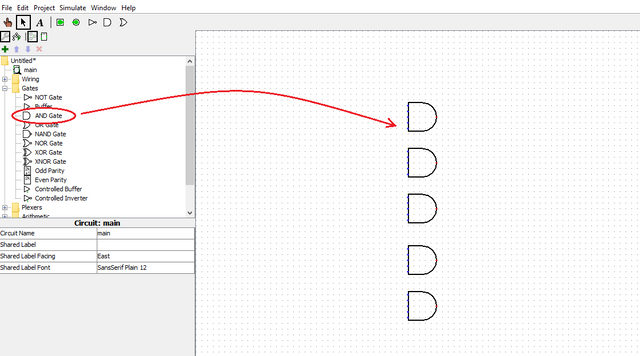
Here are the components needed.
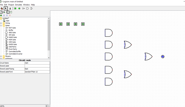
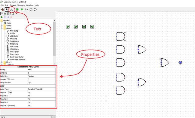
1.3 Editing the circuit
To edit the circuit, click the components and change the property table located at lower left side of window. You can also use a text box to insert text to the circuit for labeling.
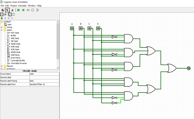
1.4 Wiring the components
To wire, click the pin of components to start and click again to end the wiring. Here is our wired logic circuit.
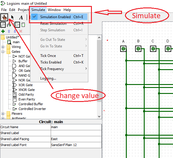
1.5 Simulation
To simulate, check the simulation enabled in the simulation menu. Select the change value command located at the upper left side of the toolbar. Change value command will able to user the change the state logic of input.
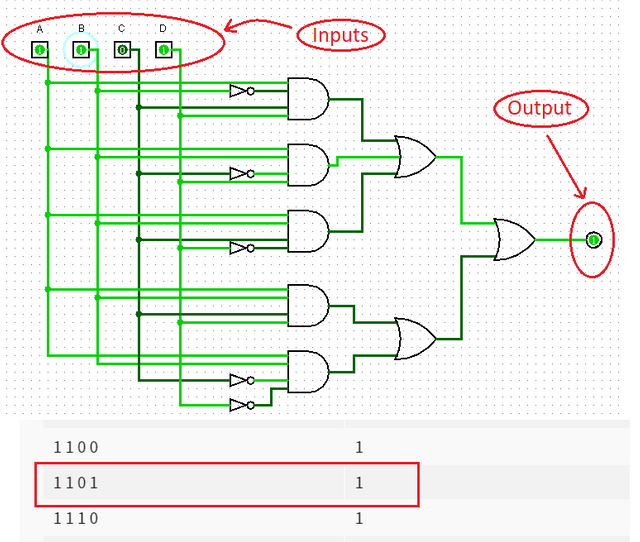
We will try to simulate some inputs and verify it with our created truth table.
Example 1.) 1 1 0 1
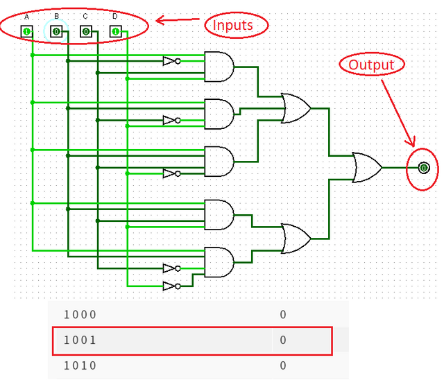
Example 2.) 1 0 0 1
Example 3.) 1 1 1 1
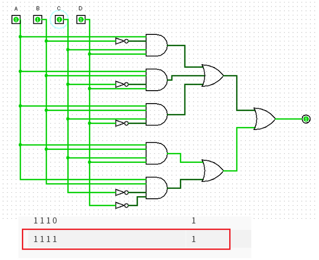
Based from the simulated example, our logic circuit's output coincides with our truth table. Therefore, our logic circuit is correct met the conditions stated in the problem and it is correct.
Equation 2(simplified)
Now we will simulate the simplified equation. f(A,B,C,D) = AbCD + AB.
This function now have much lesser components. It includes 2 AND gates, 1 inverter and 1 OR gate.
2.1 Creating the logic circuit
Follow the procedure above to create the circuit.
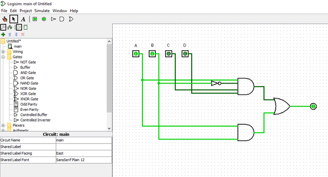
Here is our logic circuit with function equation f(A,B,C,D) = AbCD + AB.
2.2 Simulate
Same process may apply from the previous simulation
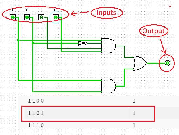
Example 1.) 1 1 0 1
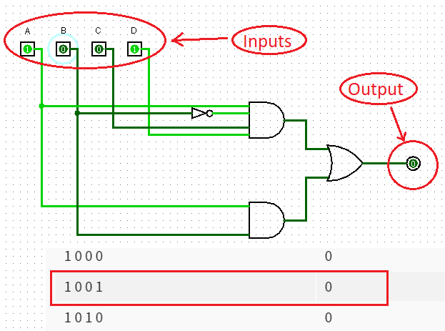
Example 2.) 1 0 0 1
Example 3.) 1 1 1 1
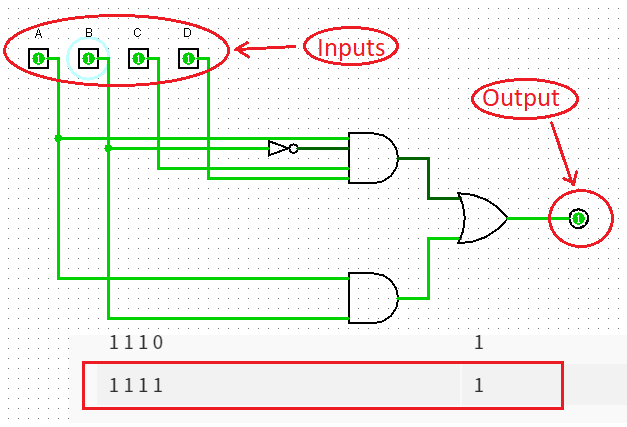
Based on the simulation example above, it has the same result with the not simplified function. Therefore, our second circuit met the condition of the problem and it is correct
Curriculum
Here are my other tutorials, you can check this out for reference. This might could help you.
- Tutorial on How to Construct Power Supply Circuit from Schematic Diagram to Breadboard Prototype and to Breadboard Construction.
- EasyEDA PCB Layout | How to transfer your schematic diagram to PCB design in EasyEDA
- How to Create Schematic and PCB Libs in EasyEDA
- Understanding Thevenin Theorem | A circuit theorem explained with the aid of circuit simulator
- Understanding Zener Diode | Investigating How Zener Diode can be Use as Voltage Regulator
Posted on Utopian.io - Rewarding Open Source Contributors
Thank you for the contribution. It has been approved.
You can contact us on Discord.
[utopian-moderator]
thank you..
Hey @thinkingmind I am @utopian-io. I have just upvoted you!
Achievements
Community-Driven Witness!
I am the first and only Steem Community-Driven Witness. Participate on Discord. Lets GROW TOGETHER!
Up-vote this comment to grow my power and help Open Source contributions like this one. Want to chat? Join me on Discord https://discord.gg/Pc8HG9x
good article, but I am a bit hard to understand the picture, sorry, not your picture is not accurate, maybe I, a little more serious learning again, to make it easier to understand, success slalu friend