QUCS Circuit Simulator:The Voltage Divider theory Explained
What Will I Learn?
- Learn all about Voltage Divider Theory
- Learn how to construct the circuit in QUCS Circuit Simulator
- Learn about simulations of the QUCS Circuit Simulator
Requirements
- Laptop or PC
- QUCS Circuit Simulator
- Resistors: 110 ohms and 55 ohms
- Voltmeter
Difficulty
- Intermediate
Tutorial Contents:
Voltage Divider is the most common circuit in almost any circuit design, its function is for producing voltage coming from the two resistors that is connected in series and will provide an output voltage lesser than the source voltage, it is also used as a signal attenuator at lower frequencies because of its ability to decrease the voltage using the resistance of the two resistors, generally it is a passive linear circuit that produces output voltage that is a fraction of its input voltage.
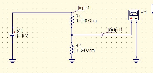
Voltage Divider Diagram:
Formula for the Voltage Divider:

Solutions in Voltage Divider:
Below is a set of solution using the voltage divider formula and ohms law for getting the reference voltages or voltages across in each resistors, for I total (total current) can be obtain by dividing the
V total (total voltage which is the source voltage from the battery 9v) by the total resistance in the circuit.
Using the formula below we are able to get a current of 0.0548 A , since the resistors are connected in series configuration means in each resistor have the same value of current.
To get the Voltages across each resistors use ohms law, finding V R1 simply multiply the value of R1 and the current across it which is equal to I total, we get a voltage of 6.036 V
the same approach in V R2 thus getting a voltage of 2.96 V which is our output.
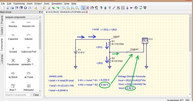
Notice that the we can also get the answer of our output using two approach the voltage divider formula and ohms law , substituting the formula for the voltage divider will result an output voltage of 2.96 V
Step by step Construction of the circuit Using QUCS Circuit Simulator:
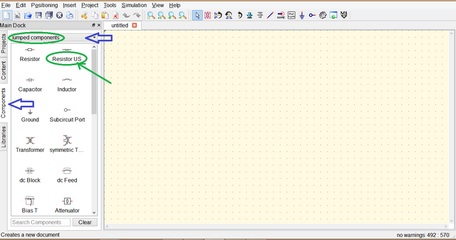
Open the QUCS Circuit Simulator, in the left side of the application there are four tabs the Libraries, Components, Content and Project to start building the project click components you will see many options just select lumped components for basic component part, then click the desired components needed, so select resistor then move the mouse to where to place it then click to paste and right click to rotate the components.
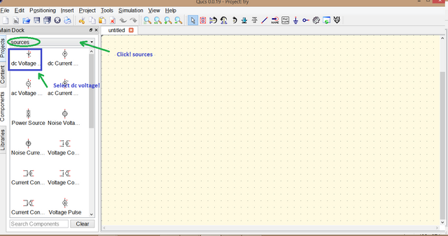
Now for Source needed since we are working in DC circuit, the same thing we did just select sources instead of lumped components then select dc voltage by clicking.
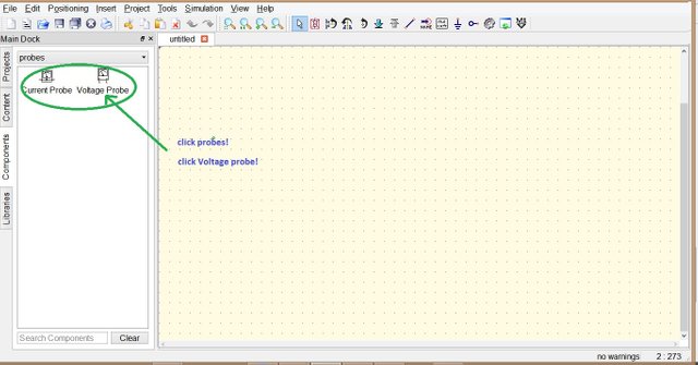
For the meters we are going to use volt meter the same as the above step just select probe then options will appear Current probe or Voltage probe click the desired meter.
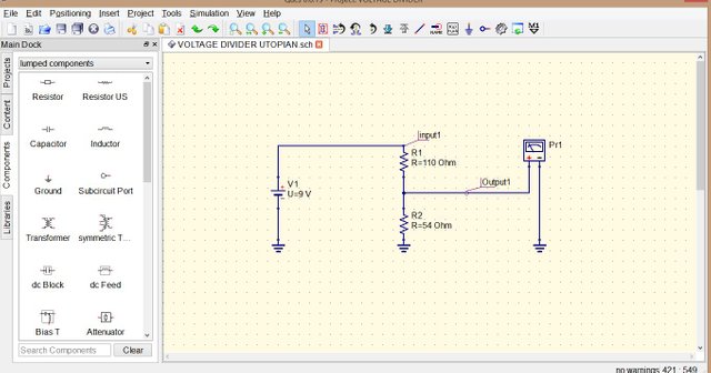
Place all the components needed in the circuit and wire them according to the Voltage Divider diagram, at the top you can see a wire drawn slant encircled with blue you can also use mirror, rotate, label, and put ground.
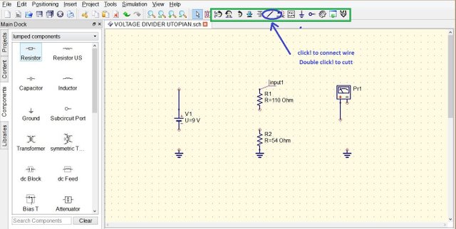
Connected Components ready to simulate.
How to use Simulation:
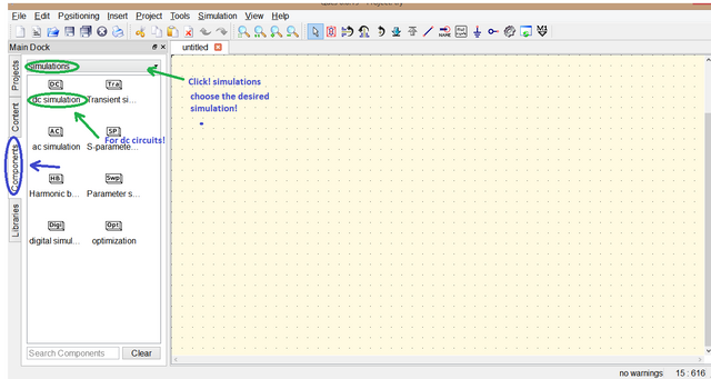
To simulate click Components select simulations then choose the desired simulation,
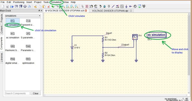
since we are working in dc circuit we are only going to use dc simulation click the dc simulation then move and place it.
after putting the dc simulation, at the top area click Simulation then select Simulate
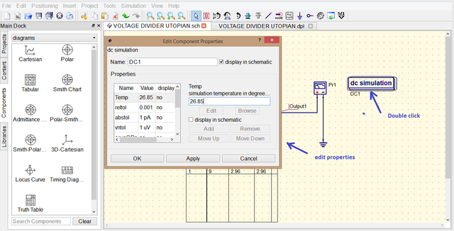
You can also edit the properties of simulation by double clicking the dc simulation in this set up it is not necessary to change the properties of simulation since we only need the output voltage.
After selecting Simulate usually a new tab will appear where you can put your simulations outcome since our desired data is not that much we are just going to use the same tab.
after simulating it will go directly in diagrams
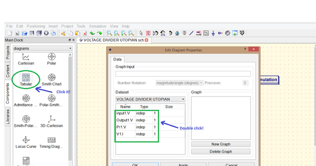
then choose Tabular since we want to display it in tabular form it will show the names that you had labelled double click each to display it in the table then click apply and ok .
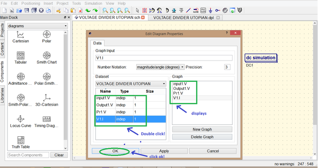
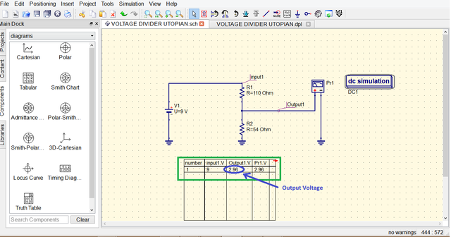
move the mouse then click to place the table. the table displays the Input1. V, Output1.V and Pr1.V the .V there represent that it is a voltage value Input1.V is the source voltage or input Pr1.V and Output1.V are just the same which is 2.96 V this proves that our calculation using the Voltage divider formula and ohms law are accurate.
Simulations:
Calculations:

The simulation using the QUCS Circuit Simulator prove that the theory of the circuit is accurate since the simulated data coincides with the result of the calculated output voltage of the voltage divider which is 2.96 V and we have also the calculated total current and voltages across in each resistor.
Curriculum
Posted on Utopian.io - Rewarding Open Source Contributors
Need help? Write a ticket on https://support.utopian.io.
Chat with us on Discord.
[utopian-moderator]