Circuit Simulator Applet simulation : "Operational Amplifiers" (www.falstad.com/circuit).
What Will I Learn?
- Inverting and Non-inverting Amplifier
- Construct and Simulate Inverting and Non-inverting amplifier
- Differentiate the Inverting and Non-inverting amplifier
Requirements
- Basic knowledge in Electronics circuit.
- Electronics Components.
- Circuit Simulator Applet
Difficulty
- Intermediate
Tutorial Contents
In this tutorial I will going to construct and simulate the basic configurations of operational amplifiers, there functions, and how they work.
Operational amplifier plays a very significant role in the field of electronics nowadays from radio, televisions to the latest technology they need amplification to work properly specially in transmission of signals where lots of attenuation occur.
What is a Non-inverting amplifier and Inverting amplifier ?
A non-inverting amplifier is an operational amplifier where the input signal or voltage is directly applied to the non-inverting input terminal making its output to be positive.
Opposite to Inverting amplifier the signal or voltage is applied to the inverting terminal input of operational amplifier which causes an output of negative values depending on the design. In this tutorial where going to construct and simulate the Inverting and Non-inverting amplifier to see the actual difference of the signal or output they have in simulation, and we are going to use the Circuit Simulator Applet.
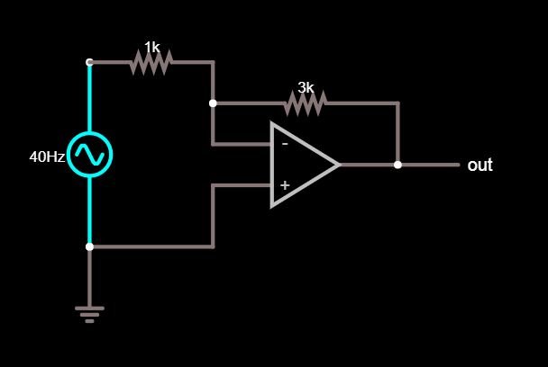
Circuit diagram:
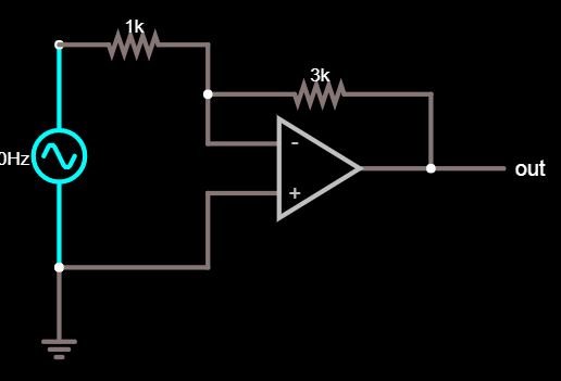
Circuit simulator applet’s diagram of Inverting amplifier.
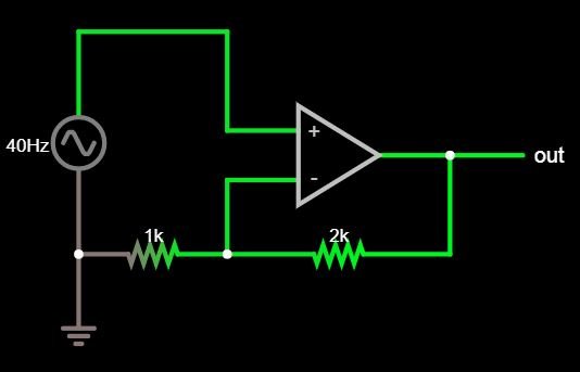
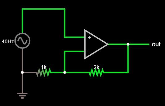
Circuit simulator applet’s diagram of Non-inverting amplifier
Electronics Components
Resistors – 1k, 2k, and 3k
IC - LM-741 operational amplifier. (Or any op-amp)
Steps:
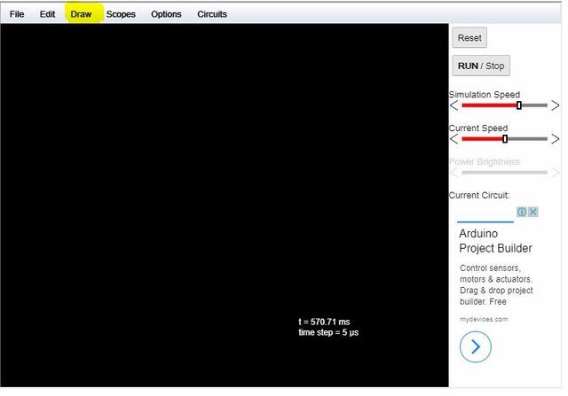
In the application you can see there a tabs like File , Edit, Draw, Scopes, Options, Circuits.
First to select for the components needed in a circuit just click Draw.
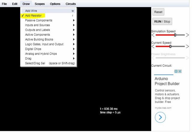
To select for a resistor just click add resistor, and
to change its resistance just double click the resistor.
Select the operational amplifier in Active Building Blocks, you can choose there options in operational amplifier.
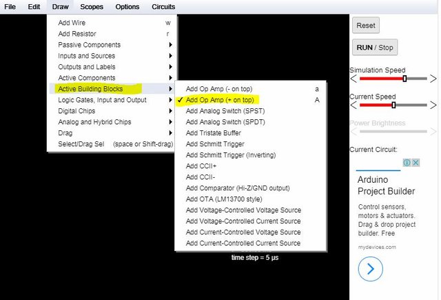
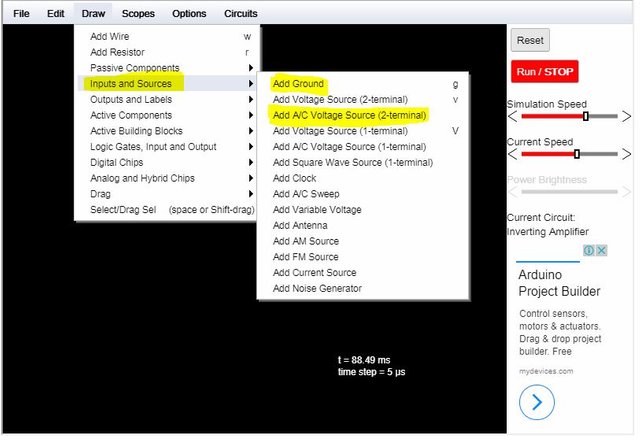
To select for Power Sources, AC signals, and Ground terminal just click from Draw - Inputs and Sources if you want to change the values of your sources just double click it.
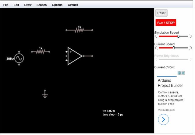
Place all the components
Connect the components with wires- just click Draw Tab then click Add wire.
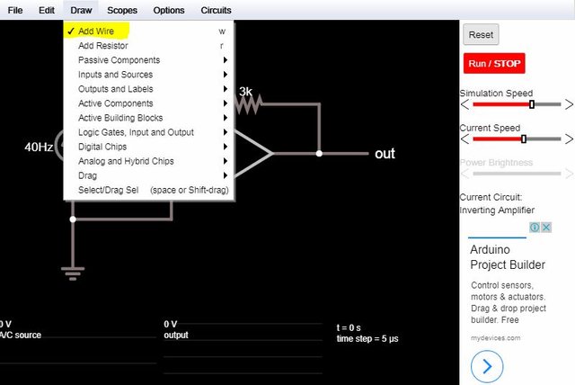
The complete circuit after connecting all the components.(In inverting amplifier circuit.)
The same steps for constructing a circuit in non-inverting configuration just follow the circuit diagram for this circuit
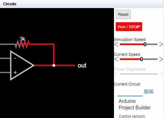
Now that our circuit is already complete click RUN/Stop located at the top right corner of the screen to start the circuit to simulate,
After the Simulation:
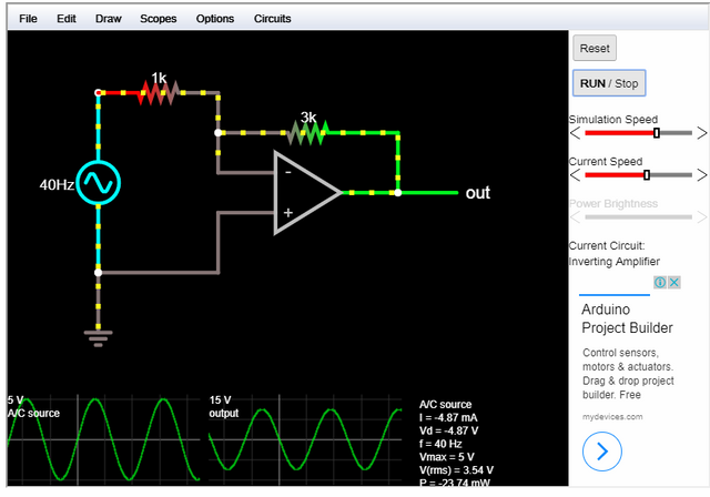
In this simulation we have achieve an amplification of the signal that we applied in the input proving that this circuit will definitely work in actual circuit,
The circuit amplify a voltage input of 5 volts to 15 volts which we can use for loads operating at 15 volts.
That's it for now everyone have a great time and follow my next tutorial this is
@leviticusjohan God bless☺☺

Posted on Utopian.io - Rewarding Open Source Contributors
Your contribution cannot be approved because it is a duplicate. It is very similar to a contribution that was already accepted here.
You can contact us on Discord.
[utopian-moderator]
Hey @roj, I just gave you a tip for your hard work on moderation. Upvote this comment to support the utopian moderators and increase your future rewards!
Congratulations @leviticusjohan! You have received a personal award!
Click on the badge to view your Board of Honor.
Do not miss the last post from @steemitboard:
Congratulations @leviticusjohan! You received a personal award!
You can view your badges on your Steem Board and compare to others on the Steem Ranking
Vote for @Steemitboard as a witness to get one more award and increased upvotes!