Introducing Sensi-Pot Open Source Automation Hardware for Indoor Gardening
Repository
https://github.com/artolabs/sensi-pot
Additional Resources
https://github.com/arduino/Arduino
https://github.com/KiCad
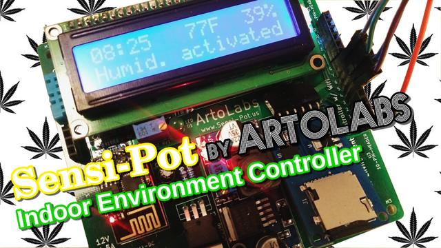
Sensi-pot is open source hardware and software
designed to help automate routine indoor garden processes such as lighting cycles, environment control, watering, and nutrient regulation. A prolific boom in the marijuana industry is taking place in Colorado, Oregon, and Washington states in the U.S. (and soon many other states) causing an increased demand for indoor gardening products. Especially in Colorado, where the winter is long and cold, most marijuana is grown indoors; necessitating equipment to help control and mimic the plant's native environment. This is especially needed for growing marijuana, which is very sensitive to heat and humidity (or lack thereof). However, most indoor gardening automation equipment is designed for big production facilities and is usually too expensive for the average grower. Sensi-pot provides electronics kits that can be easily assembled by anyone with a soldering iron, allowing the average user access to the same type of technology available to bigger growers at a fraction of the price.
Sensi-Pot Indoor Environment Controller
This is the first Sensi-Pot open source automation device made for regulating the temperature and humidity of an enclosed space, including greenhouses. Marijuana grows best when the environment is kept at a perfect balance, and this device can maintain a perfect 55% humidity and 75 degrees fahrenheit, which is perfect for marijuana. The controller can be adjusted to regulate any temperature or level of humidity. At the heart of the device is the custom circuit board, which can be ordered using the open source Gerber files, or by ordering through PCBway.com (see below for more info).
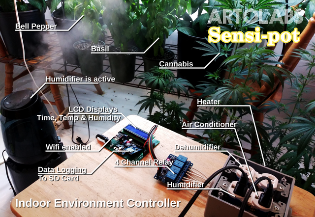
Features
Controls temperature to within 2 degrees.
Controls humidity to within 5%.
Wifi webserver shows the current temp and humidity as well as provides a manual way to active/deactivate any of the devices connected to it. You can also pause/unpause data logging from the web page as well as erase all data on the SD card.
Data logging records the temperature and humidity with a timestamp to an SD card.
Displays the current time, temperature and humidity on an LCD
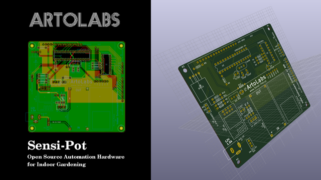
Hardware Specifications
Designed using the open source PCB design and editing software, Kicad, so any changes you'd like to make to the circuit board can easily be done using the Kicad files available on Github.
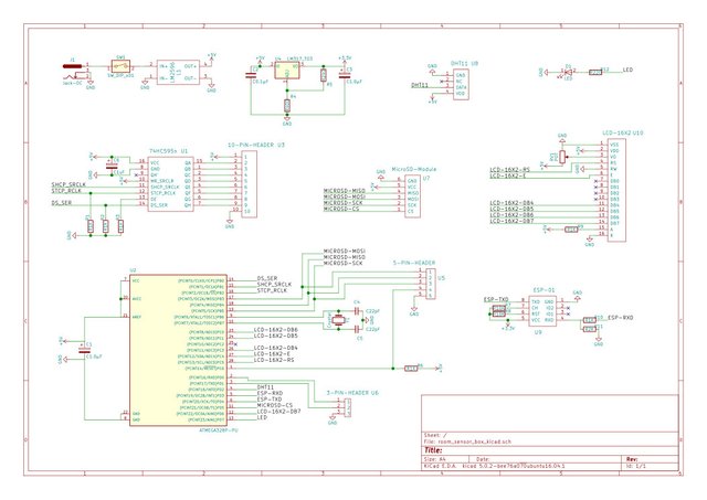
Uses the ATMEGA328P microcontroller, the same that can be found on any Arduino.
The ATMEGA328P was programmed using the open source Arduino IDE software and uses some of the Arduino libraries in it's C++ code.
Uses the ESP01 wifi module to serve a basic web page on the local network. To connect to a secured network the code must be modified slightly to include the SSID and the router password. The ATMEGA328P microcontroller communicates with the ESP01 using standard serial communication.
Can technically control up to 8 devices and simply needs an 8 channel relay to do this. The pictures in this post show the controller connected to a 4 channel relay which is capable of controlling a heater, air conditioner, humidifier and dehumidifier. The other 4 devices can include lights and fans.
Uses the DHT11 humidity and temperature sensor which can sense temperatures from 0 to 50 degrees Celsius (32 to 122 degrees Fahrenheit) +/- 2 degrees and can sense humidity from 20% to 80% +/- 5%. This can easily be replaced with no additional code with the DHT22 which has a temperature range of -40 to 125 (+/- 0.5) degrees Celsius and a humidity range of 0% to 100% (+/- 2 to 5 percent).
Uses the MicroSD module to write logging data to any standard micro SD card. The ATMEGA328P communicates with the MicroSD module using the serial peripheral interface (SPI).
Powered by the LM2596 adjustable buck converter which steps down any voltage between 9 and 34 volts to a regulated 5 volts used by the ATMEGA328P and it's peripheries. The voltage is further stepped down to 3.3 volts by the LM317 linear voltage regulator for use by the ESP01 wifi module. The Environment Controller consumes about 1.5 amps, with a peak current around 2 amps.
Includes port access to programming pins via a 5 pin header that can be used to program the Environment Controller with an Arduino. Also includes access to the RX and TX pins of the ATMEGA328P so that a serial out connection can be made to a computer (mostly used for debugging).
Software Specifications
There are actually two programs that were written to run on the Environment Controller; one for the ATMEGA328P microcontroller and one for the ESP01 wifi module which serves the webpage.
ATMEGA328P Software
Programmed using the Arduino IDE and supporting libraries.
Uses standard serial communication to transfer data between it and the ESP01 wifi module. All data is delineated by the "<" and ">" characters so that discrete amounts of data at any size can be transferred. This is very helpful as sending large amounts of data through a serial connection can be fraught with problems.
// Receives data from the ESP01 via serial connection
void recvESPData() {
    static boolean recvInProgress = false;
    static byte ndx = 0;
    char startMarker = '<'; // Delineate data
    char endMarker = '>';
    char rc;
    while (ESPserial.available() > 0 && newESPData == false) {
        rc = ESPserial.read();
        if (recvInProgress == true) {
            if (rc != endMarker) {
                receivedESPChars[ndx] = rc;
                ndx++;
                if (ndx >= numChars) {ndx = numChars – 1;}
            // Step through one character at a time
            }
            else {
                receivedESPChars[ndx] = '\0'; // terminate the string
                recvInProgress = false;
                ndx = 0;
                newESPData = true;
            }
        }
        else if (rc == startMarker) {recvInProgress = true;}
    }
}
Uses the Arduino
<SoftwareSerial.h>library to communicate to the ESP01 since the RX and TX pins are still used for debugging.Uses the Arduino
<SD.h>and<SPI.h>libraries to communicate with the MicroSD module for data logging.
myFile = SD.open("data.txt", FILE_WRITE); // Prepare SD card

…

    if (Tf > 74) {  //  If the temperature is greater than 74
      if (heaterActive) {
          heaterActive = false;
          logdevice =  cT + ":HE:0"; // cT is the timestamp, HE is code for heater
          lcd.setCursor(0, 1);
          lcd.print("Heat deactivated");
          if (myFile) {
            myFile.println(logdevice); // Log to SD card
          }
      }
      if ((Tf > 76) && (!acActive)){  //  If the temperature is greater than 76
          acActive = true;
          logdevice =  cT + ":AC:1";
          lcd.setCursor(0, 1);
          lcd.print("AC activated    ");
          if (myFile) {
            myFile.println(logdevice); // Log to SD card
          }
      }
    }
The example code block above shows how the data gets written to the SD card. Below shows how the data on the card is accessed and sent to the ESP01 to be displayed on the web page.
void getSDdata () { // Fetches the logging data from the SD card and prints it
                    // to the ESP01 via serial
    myFile = SD.open("/data.txt", FILE_READ);
    if(myFile) {
        ESPserial.print("<");
        while (myFile.available()) {
          ESPserial.write(myFile.read());
        }
        ESPserial.println(">");
        myFile.close();
    }
    else {
      lcd.setCursor(0, 1);
      lcd.print("Error reading SD");
    }
}
Uses the
<LiquidCrystal.h>library to display data on the LCD.Uses the
<SimpleDHT.h>library to fetch temperature and humidity data from the sensor.A binary system was created to utilize the shift register. Since there are eight possible devices that can be controlled, all 8 outputs of the shift register are used. A binary number contains 8 digits, where a 1 indicates that a device is on, and a 0 indicates a devices is off. Binary math (xor) is used to add all the binary states of each device together to create one binary number that represents the state of all devices.
const byte relay1 = 0x80; //0b10000000    HUMIDIFIER      green
const byte relay2 = 0x40; //0b01000000    DE-HUMIDIFIER   red
const byte relay3 = 0x20; //0b00100000    HEATER          yellow
const byte relay4 = 0x10; //0b00010000    AC              green
const byte relay5 = 0x08; //0b00001000    FAN 1
const byte relay6 = 0x04; //0b00000100    FAN 2
const byte relay7 = 0x02; //0b00000010    FAN 3
const byte relay8 = 0x01; //0b00000001    FAN 4
void activateDevice () {
  state = allOff;
  if (humidifierActive) { state = relay1; }
  if (dehumidifierActive) { state = state xor relay2; }
  if (heaterActive) { state = state xor relay3; }
  if (acActive) { state = state xor relay4; }
  state = allOn - state; // The shift register needs the opposite: On = 0, Off = 1
  writeReg(state);
}
ESP01 Software
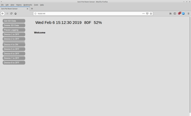
Programmed using the Arduino IDE and supporting libraries.
Contains a small amount of CSS and HTML stored in
rawliteralmemory used to display the web page.
const char* FORM_HEADER = R"rawliteral(
<div id="side"><form id='theform' action='http://)rawliteral";

const char* FORM_MIDDLE = R"rawliteral(' method='POST'>
<a href='#' onClick="document.getElementById('ARG').value='2'; document.getElementById('theform').submit();">
<div class="btn">Get SD Data</div></a>
<a href='#' onClick="document.getElementById('ARG').value='1'; document.getElementById('theform').submit();">
<div class="btn">Delete SD Data</div></a>
)rawliteral";

const char* UNPAUSED = R"rawliteral(
<a href='#' onClick="document.getElementById('ARG').value='3'; document.getElementById('theform').submit();">
<div class="btn">Pause Logging</div></a>
)rawliteral";

const char* PAUSED = R"rawliteral(
<a href='#' onClick="document.getElementById('ARG').value='3'; document.getElementById('theform').submit();">
<div class="btn">Resume Logging</div></a>
)rawliteral";

const char* FORM_FOOTER = R"rawliteral(
<input type='hidden' name='ARG' id='ARG'>
<input type='hidden' name='ARG2' id='ARG2'>
</form></div>
)rawliteral";
Uses the
<time.h>and<TimeLib.h>libraries to fetch the current time from the Internet (time.nist.gov) and sets it local time by this. This is used to create the Unix timestamps for logging, and to convert Unix timestamps to human readable days, minutes, hours and the date.The ESP01 libraries handle form submission on the web page, but a custom function was created to parse the data and commence the action.
void handleSubmit() {
  String Davalue;
  String dev;
  Davalue = server.arg("ARG");
  dev = server.arg("ARG2");
  if (Davalue == "1") {       // Delete all data on the SD card
    Serial.println("<2>");    // Returns a success code to the ATMEGA328P (only indicates code was received)
    time_t timer = time(nullptr);
    while (!Serial.available()) {
      time_t now = time(nullptr);  // Every action has a 10 second timeout period
      if (now > timer + 10) {
        startPage();
        makeSideBar();
        makePageTop();
        server.sendContent("<div id='content'><h3>Could not delete data</h3></div>");
        makePageBottom();
        dataErr = true;
        break;
      }
    }
    if (!dataErr) {
      startPage();
      makeSideBar();
      makePageTop();
      server.sendContent("<div id='content'><h3>SD card has been deleted</h3></div>");
      makePageBottom();
      dataErr = false;
    }
  }
  else if (Davalue == "2") {  // Retieves the logging data from the SD card and display it on the webpage
    Serial.print("<1>");      // Send the success code to the ATMEGA328P (only indicates code was received)
    waitForData = true;
    time_t timer = time(nullptr);  // 10 second timeout period
    while (!Serial.available()) {
      time_t now = time(nullptr);
      if (now > timer + 10) {
        startPage();
        makeSideBar();
        makePageTop();
        server.sendContent("<div id='content'><h3>Could not get data</h3></div>");
        makePageBottom();
        waitForData == false;
        break;
      }
    }
  }
  else if (Davalue == "3") {  // Pauses logging
    Serial.print("<5>");
    time_t timer = time(nullptr);   // 10 second timeout period
    while (!Serial.available()) {
      time_t now = time(nullptr);
      if (now > timer + 10) {
        startPage();
        makeSideBar();
        makePageTop();
        server.sendContent("<div id='content'><h3>Logging could not be paused</h3></div>");
        makePageBottom();
        break;
      }
    }
  }
  else if (Davalue == "4") {  // Changes the on/off state of a device when the user clicks a button
    Serial.print("<D");
    Serial.print(dev);
    Serial.print(">");
    time_t timer = time(nullptr);
    while (!Serial.available()) {
      time_t now = time(nullptr);
      if (now > timer + 10) {
        startPage();
        makeSideBar();
        makePageTop();
        server.sendContent("<div id='content'><h3>Device could not be reached</h3></div>");
        makePageBottom();
        break;
      }
    }
  }
  else {returnFail("Bad value");}
}
- The ESP01 is used by the ATMEGA328P to request the current timestamp each time data is logged.
      if (receivedChars[0] == '1') {  // The single digit code 1 requests the current time
                                      // This request is used for data logging
          time_t t = time(nullptr);
          int seconds = (int) t;
          char ds[10];
          itoa(seconds,ds,10);      // the time is sent as a UNIX timestamp
          Serial.print ("<");
          for(int i=0;i<10;i++) {
            Serial.print(ds[i]);    // Send the data back to ATMEGA328P
          }
          Serial.print (">");
      }
      else if (receivedChars[0] == '2') { // Code 2 requests the ESP01 sets it's own time to the current time
                                          // This request is used for displaying the time and date
          time_t t = time(nullptr);
          setTime(t);
          char buf[20];
          sprintf(buf,"%d-%02d-%02d %02d:%02d:%02d", year(), month(),
          day(), hour(), minute(), second());
          Serial.print ("<");
          for(int i=0;i<20;i++) {
            Serial.print(buf[i]);
          }
          Serial.print (">");
      }
Assembling The Sensi-Pot Indoor Environment Controller
The circuit board has on it a lable for every part, so assembling and soldering should be very simple. A complete BOM (Bill of Materials) is included in the Github repository so ordering all the parts should also be relatively easy. A complete set of assembly instructions along with a "how-to" video will be created in the near future.
Order this circuit board from PCBway.com
Since Artolabs uses PCBway.com for it's circuit board production you can take advantage of PCBway's share program and simply order this circuit board without the need to submit the Gerber files! You get 5 circuit boards for $5 (plus about $8 shipping), and Artolabs gets a small commission too.
ArtoLabs uses PCBway.com exclusively for small run production and prototyping. They provide outstanding customer service, and carefully review each order. It was surprising and comforting when they found some very small details I had overlooked and gave me a chance to correct my boards before manufacturing them.
Technology Stack
Sensi-Pot uses the Arduino open source library, Kicad open source PCB design software, and is written in C++.
Roadmap
This is obviously a working prototype. There are actually an incredible number of improvements planned for the Sensi-Pot Environment Controller, including: an alarm circuit (for notifying when the temperature or humidity has gone out of control, perhaps due to a malfunctioning device); an LDR (Light Detecting Resistor) to enable the LCD and LEDs to power off when the grow area is in the "lights out" phase of the day; a soft power up circuit to prevent the shift register from activating when the Environment Controller is switched on, and too many more to mention. Sensi-Pot also has in the works a Soil Sensor Array to monitor the soil conditions of up to 10 plants per array, as well as many more automation devices.
Contact
Please contact Mike (Mike-A) on Discord
https://discord.gg/97GKVFC

Your contribution has been evaluated according to Utopian policies and guidelines, as well as a predefined set of questions pertaining to the category.
To view those questions and the relevant answers related to your post, click here.
Need help? Chat with us on Discord.
[utopian-moderator]
Thank you! And I totally included my commit links in this article, as well as my next. ;)
Thank you for your review, @helo! Keep up the good work!
ǝɹǝɥ sɐʍ ɹoʇɐɹnƆ pɐW ǝɥ┴
Hello!
So glad to see you getting this out there. It's gonna be a game changer for small growers.. RS so hopefully my friends in the @canna-curate community see it..
Mad love for you Canna-gypsy.
Thanks man! This is just the beginning. ;)
Awesome work. Though I question using pot in the name. While the reason for developing this may have been growing pot indoors, it's likely useful for anyone growing any type of plants. With automated watering alone, it makes it a lot more viable for pretty much anyone to grow a few plants indoors. Speaking of which...does it support individual moisture sensors for pots? So you can tell when they need to be watered? Or individual servos to control the flow of water? I suppose even if it doesn't, it wouldn't be that hard to modify, given it's arduino.
Yeah, so the name refers to the fact that in the end you will be able to use a gardening pot loaded with sensors for automating. sensi = sensors. It's a nice play on words. ;) I'd like to make available 3d printable casings for the electronics, and of course one case will simply be a garden pot.
This environment controller is only the first thing to come out. There will be automated watering, nutrient regulation, PH testing, EC/PPM testing, etc. The works. I have soil sensors almost done. They come out next. Plus the Environment Controller already has a bunch of upgrades lined up. I also plan to make available complete kits that include all the electrical components so that all you need is a soldering iron and a few hours.
this is amazing! So glad you put this on steem! We got your back
So cool! Thanks!
Technology is catching up and the world is amazing! Awesome!
Posted using Partiko Android
Congratulations @learnelectronics! You have completed the following achievement on the Steem blockchain and have been rewarded with new badge(s) :
Click here to view your Board
If you no longer want to receive notifications, reply to this comment with the word
STOPTo support your work, I also upvoted your post!
Thank you learnelectronics! You've just received an upvote of 67% by @ArtTurtle!
Learn how I will upvote each and every one of your art and music posts
Please come visit me as I've updated my daily report with more information about my upvote value and how to get the best upvote from me.
Hi @learnelectronics!
Your post was upvoted by @steem-ua, new Steem dApp, using UserAuthority for algorithmic post curation!
Your post is eligible for our upvote, thanks to our collaboration with @utopian-io!
Feel free to join our @steem-ua Discord server
Hey, @learnelectronics!
Thanks for contributing on Utopian.
We’re already looking forward to your next contribution!
Get higher incentives and support Utopian.io!
Simply set @utopian.pay as a 5% (or higher) payout beneficiary on your contribution post (via SteemPlus or Steeditor).
Want to chat? Join us on Discord https://discord.gg/h52nFrV.
Vote for Utopian Witness!