Access control with photoelectric using fritzing with Arduino: Tutorial 2
What Will I Learn?
In this tutorial, the user will learn:
- Design of an access control using photoelectric and DC motor.
- Connection of components such as Led IR and phototransistor, transistors and 9V DC motor.
- Connection in protobard of the circuit to be used in fritzing
Requirements
Basic knowledge of Arduino programming.
- Basic knowledge of electronic devices.
- View previous tutorials.
- Resistences
- Led IR
- Fototransistor
- Motor DC 9V
- NPN transistors
- Battery 9V
- Arduino Uno Card
Difficulty
- Intermediate
Tutorial Contents
Greetings, this is a contribution from @gasuba for Utopian of the Open Source. In the present tutorial the photodetector is used, in which the current of the base of the transistor varies according to the light it receives, its principle is similar to a photocell. The Fritzing program is used to make the prototype connection in the protoboard to perform the tests, it should be noted that in this project the Arduino Uno platform is used for the acquisition of a signal emitted by the photoelectric.
The project tries to realize the control of access of people for an office that requires to automate or to control the entrance of people that enter and leave. The principle is based on a light emitter and a photodetector that receives it, when a person enters or leaves the office disturbs the light and therefore the engine acts to open or close the door.
Step 1.
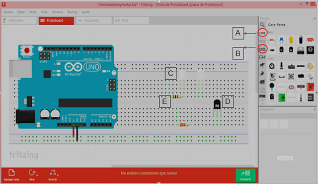
We select the devices to be used, in this case we add: an IR LED, a phototransistor, an NPN transistor and two resistors of 1kΩ and 220Ω, this will be our first design stage to sense the entry and exit of people. The components that refer to the figure are:
A. Search of electronic devices.
B. Finder of the Arduino boards, in this case Arduino Uno.
C. Led IR and forotransistor.
D. NPN Transistor.
E. Resistances.
Step 2.
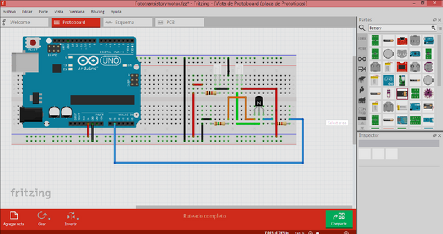
We make the connection so that the Arduino has as analog input on pin A1 the signal that comes from the phototransistor that varies depending on the light it detects, which will be disturbed by the entry and exit of people in the office. The following picture shows the connection of this first part of the circuit:
Step 3.
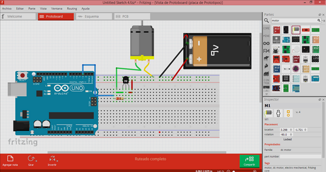
The second stage of the circuit will consist of the control of a DC motor, in this case the motor will be powered by a voltage of 9V, once the phototransistor detects high light intensity, which translates into a sufficient base current for the phototransistor enter your point of operation and deactivate the engine when there is an obstacle in the emission and reception of light. The following figure shows the connection of the motor to the output of pin 3 of Arduino, which will write on the pin a high or low in the base of the transistor according to the programming of the Arduino.
Step 4.
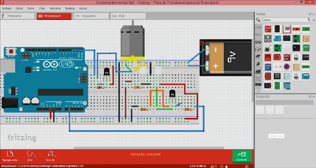
We connect the final circuit for the application that we want to develop. Observe the following figure:
Step 5.
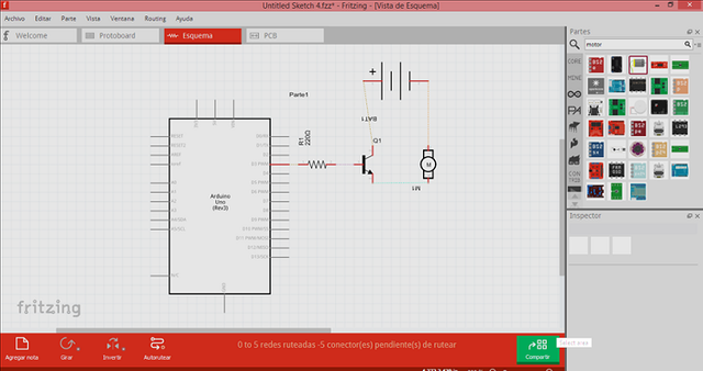
Then the schematic of the 9V DC motor connection is shown. We will take into account that only in this case the motor will be able to control the speed, since if we want to change the direction of rotation we must use a driver or H bridge, which also allows us to protect the Arduino board from the current that the motor consumes.
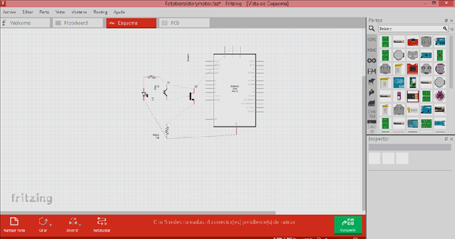
There is also the echematic of the first part of the circuit, which allows to obtain the sensing of the input signal.
Finally I present the Arduino code. Once we have the circuit connection in fritzing we proceed to establish it in our breadboard and record the following program in the Arduino board:
float A1=1;
float v;
float Voltaje;
void setup()
{
  pinMode(3, OUTPUT);
  Serial.begin(9600);
}

void loop()
{

  v=analogRead(A1);
  Voltaje=v /20;
  Serial.println(v);
  Serial.println(Voltaje);
  if(Voltaje<1){
  digitalWrite(3, LOW);

  }
    else{
  if(Voltaje>2.5){
  digitalWrite(3, HIGH);

   }
  }
 }
Thank you all for your time and attention, I hope it is very useful for your projects ... See you in the next tutorial.
Curriculum
- Introducción a Fritzing utilizando un circuito básico con LDR
- Control of an alarm with LEDs and the Arduino Uno card using Fritzing: Tutorial 1.
Posted on Utopian.io - Rewarding Open Source Contributors
Thank you for the contribution. It has been approved.
You can contact us on Discord.
[utopian-moderator]
Hey @gasuba I am @utopian-io. I have just upvoted you!
Achievements
Suggestions
Get Noticed!
Community-Driven Witness!
I am the first and only Steem Community-Driven Witness. Participate on Discord. Lets GROW TOGETHER!
Up-vote this comment to grow my power and help Open Source contributions like this one. Want to chat? Join me on Discord https://discord.gg/Pc8HG9x
Mucho éxito @gasuba :D
Thanks for posting that. The code is great. Im new ti fritzing...always something to learn!
Greetings, the important thing is to be able to generate this knowledge for all lovers of electronics .... Thank you for commenting.
Excelente contribucion @gasuba le he dado resteem. Te visito desde el TOP 5 de #steemfamilyhi. Saludos
Excelente contribucion @gasuba le he dado resteem. Te visito desde el TOP 5 de #steemfamilyhi. Saludo
Te visito desde el TOP 5 de #steemfamilyhi.
Buen aporte a la comunidad. Saludos
fascinante la ingenieria electronica saludos desde #steemfamilyhi