Sequential circuit synthesise modeling on "Digital"
What Will I Learn?
In this tutorial, readers:
- will learn the basics sequential logical circuits
- will learn implementation of sequential circuit synthesise on "Digital"
- will be able to construct any sequential logic circuit on the software
Requirements
In order to complete the tutorial, readers would have:
- Basic idea about logic designing
- Basic truth table implementation skills
- a working PC, "Digital" software
Difficulty
- Intermediate
Tutorial Contents
In this tutorial, we will cover sequential circuit analysis & synthesis on the software "Digital". So far we have worked on combinational circuits (not completely), so before going into software details, I will talk about basics of sequential circuits, and the differences, then will explain how "synthesise" sequential circuit with an example circuit.
Episode 1: What is sequential logic circuits?
Sequential logic circuits are the kind of circuits whose output states of the circuit are depend on the previous states, which means that circuit has internal "memory" inside it. Those circuits are generally controlled by clock signals, so as a users we do not need to switch inputs/outputs. At each clock signal(positive cycle or negative cycle) the circuit goes next state from different one, the states are depended on the previous ones, and the logic components inside the circuit.
(We may think that those circuits has a type of feedback inside it, so output is under control by the previous steps.)
In real world applications, sequential circuits are very common, so knowing them is vital for each digital circuit designers. In this tutorial I will show how to construct complex sequential circuits by the help of the software "Digital".
Episode 2:Construction of sequential circuits in Digital
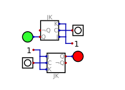
There are several ways to construct, we can manually construct sequential circuits (as I have done here) or we can simply use Synthesise function on the software.
In this tutorial, I will explain constructing sequential circuits by using this function. Explanation will be step-by-step.
- 1- Opening the synthesise function,
As a first step, we will open the function
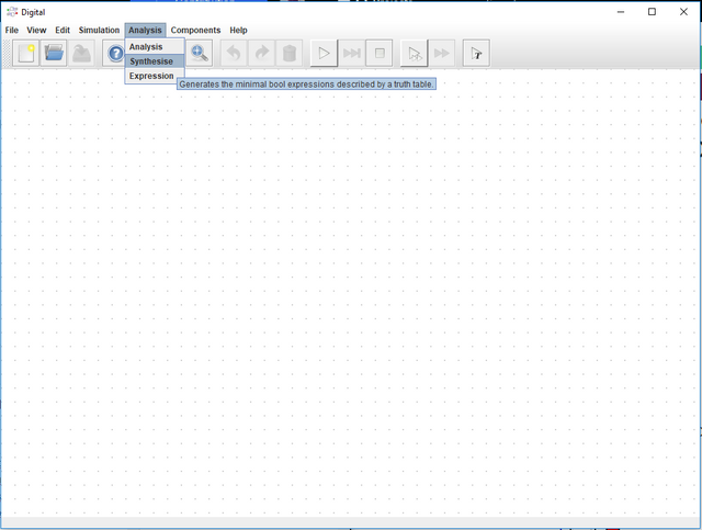
Following window will appear:
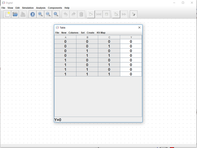
- 2- Configuring Sequential Logic Circuit
In order to pass sequential circuit, we need to click:
-->New ---> Sequential --> Choose any number of variables. ( I will work on 4 input system so 4 is selected)
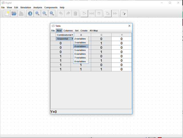
When it is clicked, following window will appear:
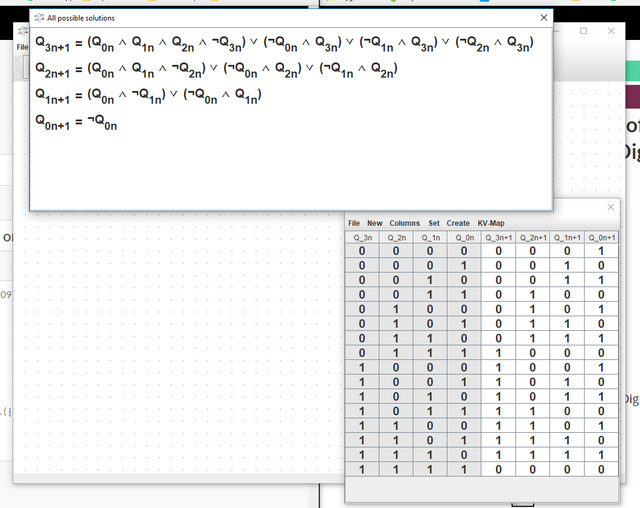
From here, we can see the truth table and all possible selections. Lets focus on truth table.
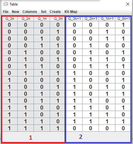
From section 1, we can see the PRESENT STATES and on section 2, we can see FUTURE STATES of the circuits, the logical connection between them are made by logical components.
Now, I want to construct a sequential circuit whose state is the following:
** 4-input counter circuit that counts in MODULO 7 which means that in every 7 state the circuit will behave with same output. **
To apply this condition, we need to play with TRUTH TABLE that I have provided above.Any value can be change when just clicking and selecting just as below:
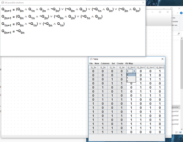
In the figure, I am changing the value of next state of Q3. In order to have the circuit that I have stated above, the sequence should be in this form:
0000 ---> 0
0001 ---> 1
0010 ---> 2
0011 ---> 3
0100 ---> 4
0101 --->5
0110 ---> 6
0000 ---> 0
0001 ---> 1
0010 ---> 2
...
And it goes by that order.
To obtain that sequence, we need to adjust NEXT STATES on the truth table just given below.
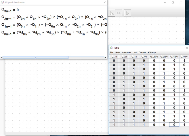
Notice that ALL POSSIBLE SOLUTIONS section is also changed with each change in the truth table.
In fact, here only the first 7 state is important for us since our circuit does not use the next states.
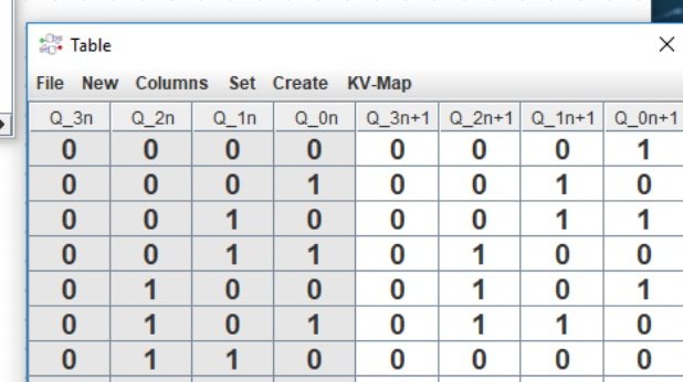
Focusing on that table will give the resultant circuit as I have stated above.
This is a very important point. Readers should understand it before going further.
- 3- Obtaining the circuit
In order to obtain the circuit, we need to click
Create ---> Circuit with JK Flip-Flops
The result is given below:
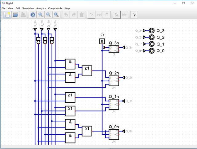
This circuit is nothing but a sequential circuit, just like I have created in my previous tutorials. Only difference is the presentation of states, which should not confuse the reader.
- 4- (Optional) Changing Clock Frequency
In order to have more slow analysis, I will change the clock frequency just by right clicking it.
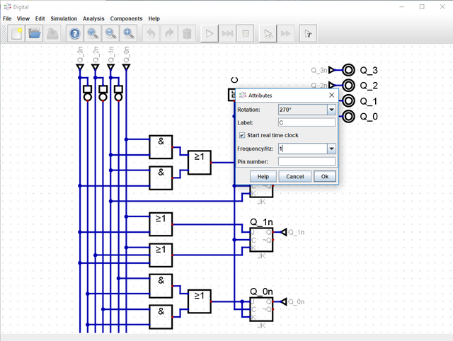
Episode 3:Analysis of the sequential circuit
The result of the simulation is given below:
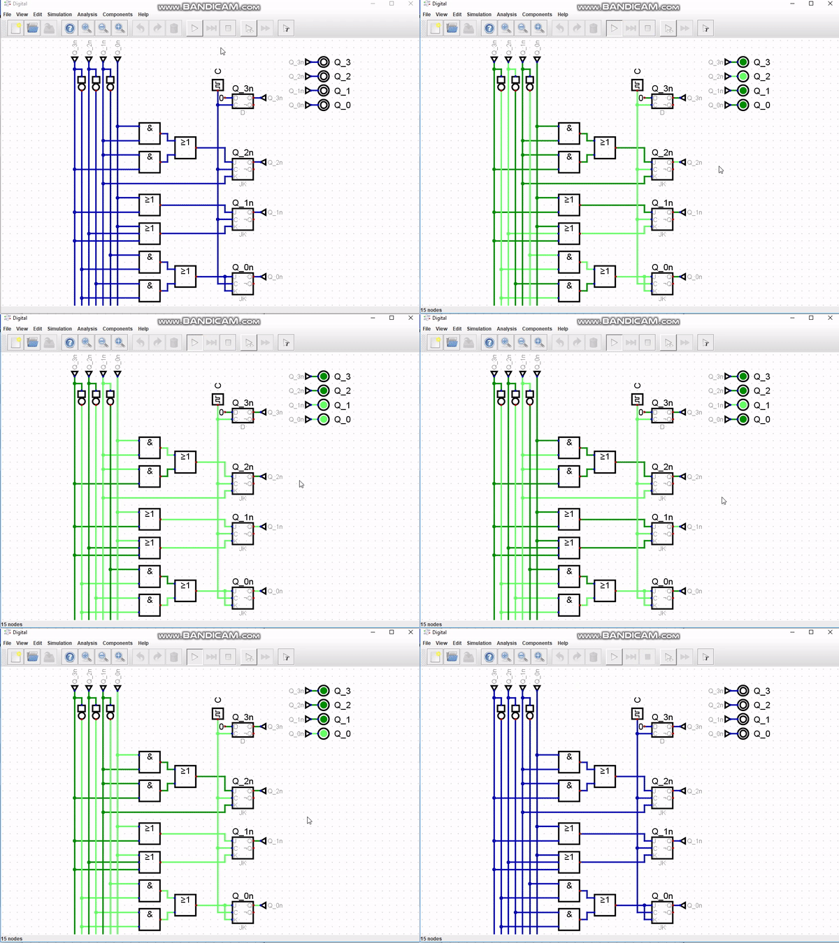
From here, we can see that the circuit works perfectly.
I have provided the files for this tutorial here. I highly recommend that the reader should work on the files that I have provided and try to understand the basics of the circuit & software. It will be benefical for he/she.
This is the end for this tutorial.Hope that you like it.
Digital is a really effective and easy to learn software, I highly recommend this software for the one who wants to make simulation in digital circuits especially. If you have any questions, please feel free to ask me on Discord (Escorn#4114)
Curriculum
I have provided the previous tutorials that I have prepared for the community:
| SimulIDE | Caneda | Digital | LogiJS |
|---|---|---|---|
| Part 1 | Part 1 | Part 1 | Part 1 |
| Part 2 | Part 2 | Part 2 | |
| Part 3 | Part 3 | Part 3 | |
| Part 4 | Part 4 | Part 4 | |
| - | Part 5 | Part 5 | |
| - | Part 6 | Part6 | |
| - | Part 7 | Part 7 | |
| - | - | Part 8 | |
| - | - | Part 9 |
Posted on Utopian.io - Rewarding Open Source Contributors
Thank you for the contribution. It has been approved.
You can contact us on Discord.
[utopian-moderator]
Thanks :)
Hey @escorn I am @utopian-io. I have just upvoted you!
Achievements
Community-Driven Witness!
I am the first and only Steem Community-Driven Witness. Participate on Discord. Lets GROW TOGETHER!
Up-vote this comment to grow my power and help Open Source contributions like this one. Want to chat? Join me on Discord https://discord.gg/Pc8HG9x