Voltage amplifier using bipolar transistor, with the Oregano simulator.
What Will I Learn?
In this tutorial you will learn:
Work with electronic devices of three terminals,
Use bipolar transistors to amplify signals.
Know the benefits of the Oregano simulator for the analysis of analog circuits.
Requirements
Knowledge of electronics
Analysis and design of electronic circuits.
Know the structure of electronic circuit simulators.
Difficulty
- Intermediate
Tutorial Contents
This is a material created by the @edagmi account for utopian-io, used with electronic engineering students in a university in Venezuela.
Voltage amplifiers are circuits required in analog electronics to perform signal conditioning. Amplifiers are very common when it is required to handle signals of very low amplitude that can come from some sensor of a physical signal. There are many simulators of electronic devices in the market, but in the area of free software we are designing electronic circuits using the tools available to developers and verifying their benefits and deficiency.
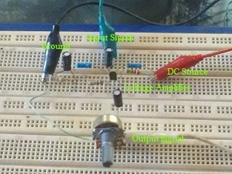
Source: @edagmi
Oregano is an electronic circuit simulator that presents a platform very similar to simulators in the Pspice code format. It is important to mention that currently there is little information about the use of this simulator with different types of electronic circuits, which allow circuit designers to use another alternative tool for the simulation and verification of their designs.
In this opportunity we will create in oregano the procedure for the design of the signal amplifier circuit and we will verify its potential for the analysis of the circuit.
Oregano presents an area to create the schematic circuits, different libraries of components, sources, generators and signal meters. Oregano only works in the Linux system, unlike other simulators it is important to keep in mind that you must download some libraries to work with certain types of elements. We will proceed to design the voltage amplifier using oregano, this uses the family of BJT transistor curves where you can select the device that is required to generate an amplifier. The following figure shows the incrustation of components in the schematic of the circuit:
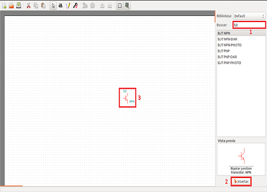
The amplifiers with BJT transistors, can be designed to increase the output of current, voltage or power of a given circuit, the required amplifier is a voltage amplifier that is used in the conditioning of small signals coming from some type of sensor. A Common Emitter configuration is established.
The configuration requires a number of elements, resistive and capacitive with commercial values that define the point of operation of the transistor. The Oregano allows each of the elements of the circuit to be structured by connection node, as shown in the following figure:
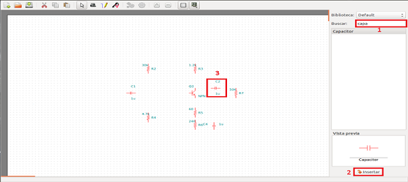
The circuit has a polarization mode known as a voltage divider, the connection of the elements with the ground reference points of the sources and the terminals of the circuit is made, leaving the diagram as seen in the image:
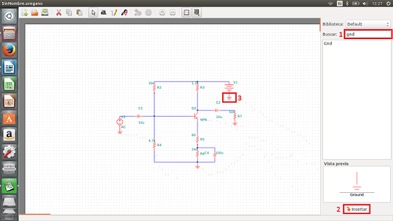
The configuration is known as the Common Emitter, since it has the reference point in the Emitter terminal. This configuration requires the input signal in the terminal of the transistor Base and the output signal in the Collector terminal of the transistor. These terminals are defined as Vi and Vo. Observe the configuration in the following image:
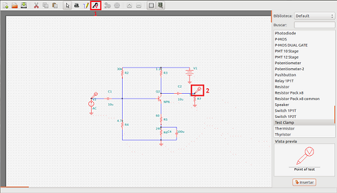
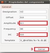
An input sine wave is configured with the following values:
Amplitude: 0.1 Volts.
Frequency: 60 Hertz.
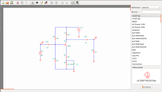
The program allows to include another type of wave and add a phase angle to the signal. In the following figure we can see the final design of the circuit with the test nodes and with the input signal of the circuit.
The simulation is run for a transient analysis of the input and output signals. The signals as a function of time allow to see the waveform of the circuit. In the following image you can see the configuration of the time that must exceed the frequency of the signal to visualize the complete wave of both signals.

The waveforms of the test nodes Vi and Vo are observed in the following image, in a sweep as a function of time for 200 ms. Vi is displayed in green and Vo in white. The sweep in the Oregano satisfies the requirements of sampling frequency for better visualization of the signal.
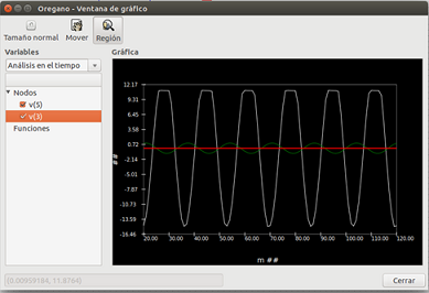
Analysis of the response of the circuit:
The output wave drawn in white represents the output of the voltage amplifier, with a gain value (AV) greater than 15, that is:
Vo = -AV * Vi
Where the negative sign represents a 180 ° phase angle between the input signal and the output signal. The capacitors must have high commercial values, so that at the frequency of the circuit, they connect the input and output signals.
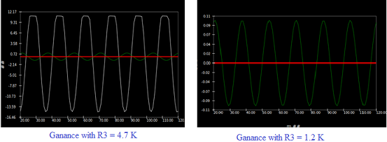
The resistance of the collector R3 can directly influence the voltage gain factor of the circuit. In the image we see the response of the circuit for variations of R3.
Thank you for your attention and I hope you find this material useful.
Posted on Utopian.io - Rewarding Open Source Contributors
Thank you for the contribution. It has been approved.
You can contact us on Discord.
[utopian-moderator]
First time seeing a tutorial on electronics, how can we use this ?
What do you mean?
I meant could we use in some real life practice ?
You can input an audio signal to the amplifier and connect a speaker to output.
The circuits of these tutorials are practical applications of use in electronic design and represented with open source simulators, for this analog electronic case. Thanks for your comments!
Hey @edagmi I am @utopian-io. I have just upvoted you!
Achievements
Suggestions
Get Noticed!
Community-Driven Witness!
I am the first and only Steem Community-Driven Witness. Participate on Discord. Lets GROW TOGETHER!
Up-vote this comment to grow my power and help Open Source contributions like this one. Want to chat? Join me on Discord https://discord.gg/Pc8HG9x