Getting Started with Arduino Uno : Electronics Project #1 - Led Light chaser
Overview ✌
Basically, to make the light chaser, we will have to turn on one LED at a time while the other LED is off. The process or program would be like this:
➣2nd LED on, 1st, 3rd, 4th and 5th are off
➣3rd LED on, 1st, 2nd, 4th and 5th are off
➣4th LED on, 1st, 2nd, 3rd and 5th are off
➣5th LED on, 1st, 2nd, 3rd and 4th are off
How? Well, we will use for loop function to address that problem. And we will also use a potentiometer to determine the delay of each LED.
More info below
👇
👇
✔ Tasks to do:
⓵ We will know what is LED Light Chaser. 👍
⓶ I'll introduce to you the materials needed for this project. 👍
⓷ Descriptions of each materials 👍
⓸ To show the circuit connections using Fritzing. Also in its real world application. 👍
⓹ What codes are being used in this project. 👍
♦What is Led Light Chaser?
An LED light chaser is loosely defined as a system where LEDs follow one another in a certain pattern.
So what does an Led light chaser do?
A light chaser can be used to create lighting animation sequences to attract attention for advertising and promotion, such as the one we saw in some stores and malls. In addition, it can be used to create pleasing effects for entertainment as well.
Others might find this not that helpful, but for some people who studies electronics, it is really important to know Led light chaser for this is one of the basic fundamentals in learning arduino programming. Just like me, an Electronics Engineering student who really find this important and interesting because with this little knowledge, I can improve my skills in the near future.
There are many excellent electronic projects that you can do with the help of arduino, but in order for you to maximize that passion to know about the world of microcontrollers, you need to know first the basics and Led Light Chaser is indeed one of them.
♦Materials Used
| Name of Materials | Quantity | Visual Representation |
|---|---|---|
| Arduino Uno | 1pc. | 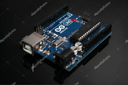 Source Source |
| LED | 5pcs. | .jpeg) Source Source |
| Breadboard | 1pc. | 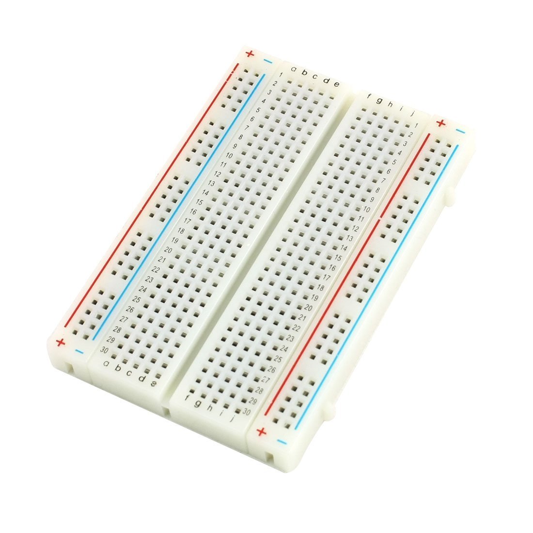 Source Source |
| Potentiometer | 1pc.(100kΩ) | .jpeg) Source Source |
| Jumper wires | 15pcs.(more or less) | 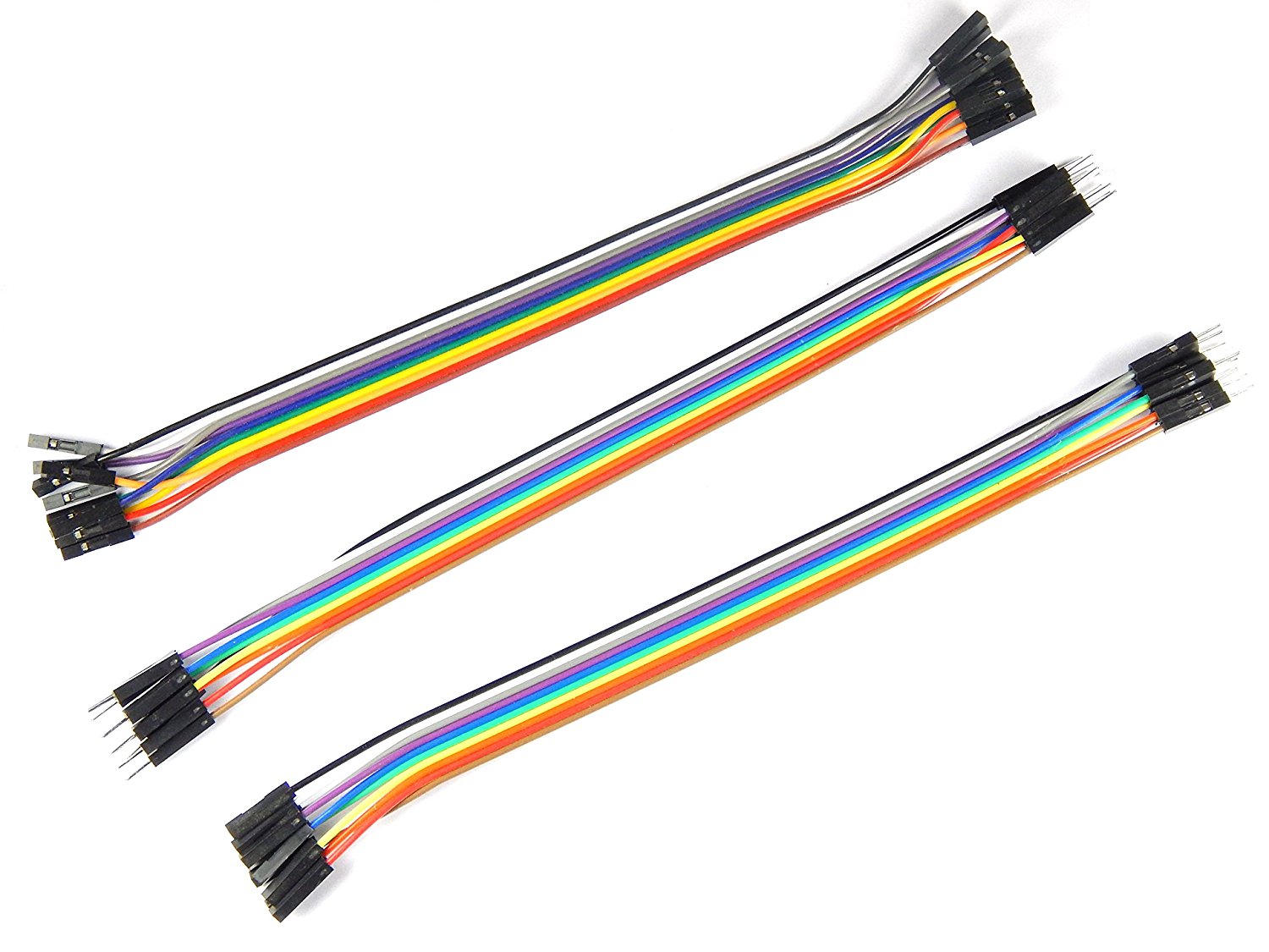 Source Source |
| Resistors | 5pcs(470Ω) | 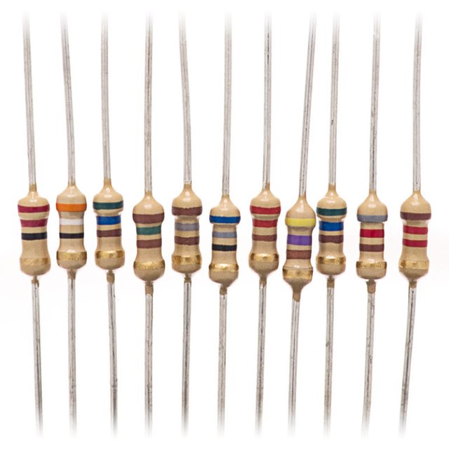 Source Source |
♦Description of each materials
Arduino ➨ is an open-source platform used for building electronics projects. Arduino consists of both a physical programmable circuit board (often referred to as a microcontroller) and a piece of software, or IDE (Integrated Development Environment) that runs on your computer, used to write and upload computer code to the physical board.
LED ➨ is a two-lead semiconductor light source. It is a p–n junction diode that emits light when activated.
Breadboard ➨ is a solderless device for temporary prototype with electronics and test circuit designs.
Potentiometer ➨ is a three-terminal resistor with a sliding or rotating contact that forms an adjustable voltage divider. If only two terminals are used, one end and the wiper, it acts as a variable resistor or rheostat.
Jumper wires ➨ are cables with connector pin at both end. They make components easier to connect.
Resistor ➨ is a passive two-terminal electrical component that reduces current flow, adjust signal levels, to divide voltages, bias active elements, and terminate transmission lines, among other uses.
Softwares used ✔
➧ Fritzing
➧ Arduino - download here
♦Circuit connection using Fritzing. And its real application.
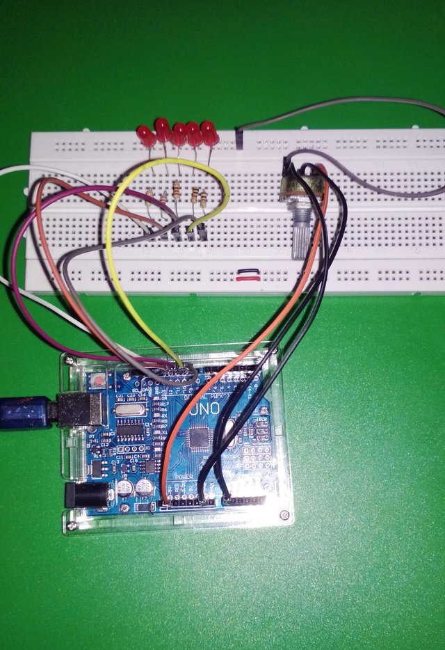
This is the testing of components connected to Arduino using Fritzing. Although I'm only using the Beta software and not the original software, the function is still the same.
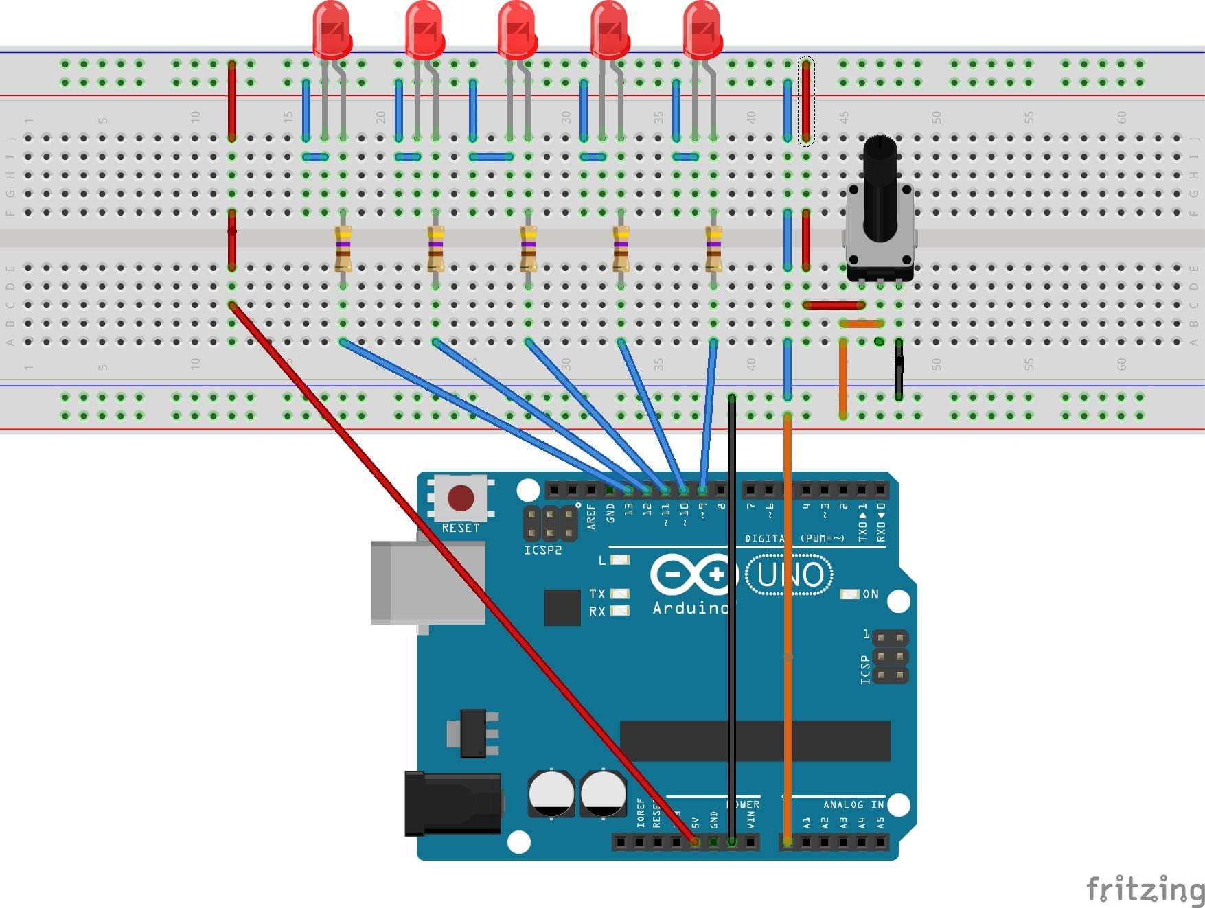
I used LED1-LED5 output display at D9-D13 pins of the Arduino Uno. And A0 pin is used to read analog voltage from potentiometer.
♦Arduino Codes for this project
int LED1 = 9;
int LED2 = 10;
int LED3 = 11;
int LED4 = 12;
int LED5 = 13;
int delay1;
void setup() {
 pinMode(LED1, OUTPUT);
 pinMode(LED2, OUTPUT);
 pinMode(LED3, OUTPUT);
 pinMode(LED4, OUTPUT);
 pinMode(LED5, OUTPUT);
 pinMode(A0, INPUT);
 pinMode(9, OUTPUT);
}

void loop() {

 delay1 = analogRead(A0);
 //  analogWrite(9, val / 4);
 digitalWrite(LED1, HIGH);
 digitalWrite(LED2, LOW);
 digitalWrite(LED3, LOW);
 digitalWrite(LED4, LOW);
 digitalWrite(LED5, LOW);
 delay(delay1);
 digitalWrite(LED1, LOW);
 digitalWrite(LED2, HIGH);
 digitalWrite(LED3, LOW);
 digitalWrite(LED4, LOW);
 digitalWrite(LED5, LOW);
 delay(delay1);
 digitalWrite(LED1, LOW);
 digitalWrite(LED2, LOW);
 digitalWrite(LED3, HIGH);
 digitalWrite(LED4, LOW);
 digitalWrite(LED5, LOW);
 delay(delay1);
 digitalWrite(LED1, LOW);
 digitalWrite(LED2, LOW);
 digitalWrite(LED3, LOW);
 digitalWrite(LED4, HIGH);
 digitalWrite(LED5, LOW);
 delay(delay1);
 digitalWrite(LED1, LOW);
 digitalWrite(LED2, LOW);
 digitalWrite(LED3, LOW);
 digitalWrite(LED4, LOW);
 digitalWrite(LED5, HIGH);
 delay(delay1);
}
As we can see, the codes above is quite long. For this to become shorter and for us to understand easier, we need to apply for Loop function.
Here are the new codes after applying For Loop:
int delay1;
void setup()
{
  for (int i = 9; i <= 13; i++)
  {
    pinMode(i, OUTPUT);
  }
}

void loop()
{
  delay1 = analogRead(A0);

  {
    for (int i = 9; i <= 13; i++)
    {
      digitalWrite(i, HIGH);
      delay(delay1);
      digitalWrite(i, LOW);
    }
  }
}
After applying for Loop function, the codes are now shorter and much easier to interpret. And they still functions the same.
➠Short explanation about the new codes with for loop function.
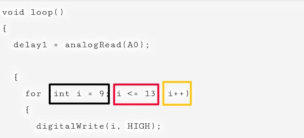
For Loop is used to repeat block of codes which will turn ON and OFF the LED'S. Variable "i" is used to determine which LED will turned on. Whenever the for loop ends, "i" will be incremented by 1 which will caused the next LED to turned ON. This continues up until until 5 loops because we only have 5 LED'S.
BLACK : The variable “i” start is “9”
RED : Define variable “i” max to “13”
YELLOW : Define step up variable “i”
It means that variable "i" is incremented by step. (9-13)
♦The actual video of this project(Final Output)
I uploaded this video in my YouTube channel but I set it on private.
Purpose of this post
Of course, the main purpose of this post is to help you how to make a simple Led Light Chaser using Arduino and how to program it using different methods depending on your taste of choice. This project is not limited to this application only. You can customize it and add more LED'S to be more attractive. It really depends on you.
I hope that this post/tutorial will be helpful to everyone specially to students like me who really love electronics. Good day ahead ❗
Yours truly, 😊
@ruelx

Congratulations! This post has been upvoted by SteemMakers. We are a community based project that aims to support makers and DIYers on the blockchain in every way possible. Find out more about us on our website: www.steemmakers.com.
If you like our work, please consider upvoting this comment to support the growth of our community. Thank you.
Thank you so much @steemmakers.
This post has received a 0.44% upvote from thanks to: @ruelx.
For more information, click here!!!!
Try the new Minnowhelper Bots for more information here
Help support @minnowhelper and the bot tracker by voting for @yabapmatt for Steem witness! To vote, click the button below or go to https://steemit.com/~witnesses and find @yabapmatt in the list and click the upvote icon. Thank you.
Voting for @yabapmatt