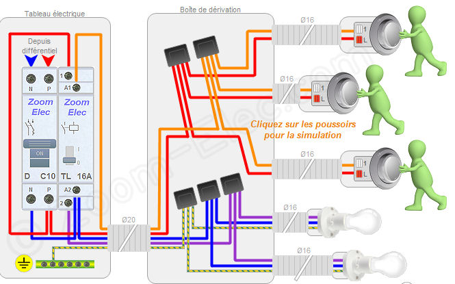
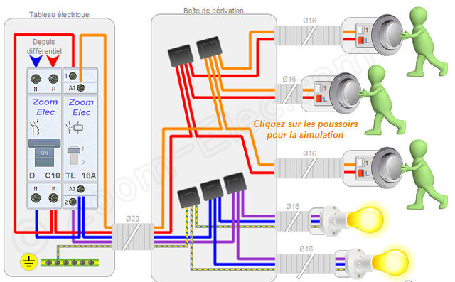
Wiring and connection of a remote control and push buttons
This diagram shows the wiring of a single-pole remote relay and push buttons without a junction box. The controls as well as the light point (s). Will be plugged into a box-to-box enclosure (depending on the depth of the switchgear housing, it is not recommended to have more than 2 ducts).
WARNING: the electrical standard permits only 8 points of use per circuit
--How to Wire the Installation of the Electrical Circuit of a Remote Switch and Push Buttons:
1.Pushbuttons: From the remote switch to the first push button housing,
Use the same configuration for the other pushbuttons, either from housing to housing or from housing to remote control
Depending on the configuration of your site.
2.Lamp: From the remote to the point of use,
• 1 wire for the return of the contact of the impulse switch, all colors other than blue or green / yellow (usually colored different from red for better marking, violet in the example)
• 1 wire for the neutral, blue color of section 1.5mm²
• 1 ground wire, green / yellow color with 1.5mm² section
3.Transplanting the 2nd lamp: From the first point of use to the second point of use
• 1 thread for the continuity of the return, same colors as used previously, of section 1.5mm²
• 1 wire for the continuity of the neutral, blue color of section 1.5mm²
• 1 wire for earth continuity, color green / yellow with cross-section 1.5mm²
4.For one or more additional duplicate (s), repeat paragraph 3
5. Powering the remote control:
• 1 wire for the phase, all colors other than blue or green / yellow (usually red) with cross-section 1.5mm²
• 1 wire for the neutral, blue color of section 1.5mm²
 Once the circuit is established, all you have to do is connect and install the pushbuttons, connect the DCL boxes and wire the remote switch:
