RUNNING LED LIGHTS using IC's (74LS154, 74LS193 & 555 timer)
💡Objective:
❖ To bring you back about creating manual operation of RUNNING LIGHTS.
❖ To teach you on how to come up on a manual operating RUNNING LIGHTS using a certain IC's for its operation.
❖ To teach you what is astable circuit using 555 timer and what is its function on creating RUNNING LIGHTS.
OVERVIEW OF THE PROJECT 🔎
In this tutorial, I will be showing you the step by step process on how to construct a running led lights using different IC's. Instead of arduino, using of Integrated Circuits can also be a good designing technique for industrial circuitry. The explanation of functions of the different IC's were also inculcated in this tutorial. But first, what is a running lights? It is said to be the simultaneous activation of LED lights patterned with the use of Integrated Circuits or other relevant components prior to the said project.
🔧Materials Used
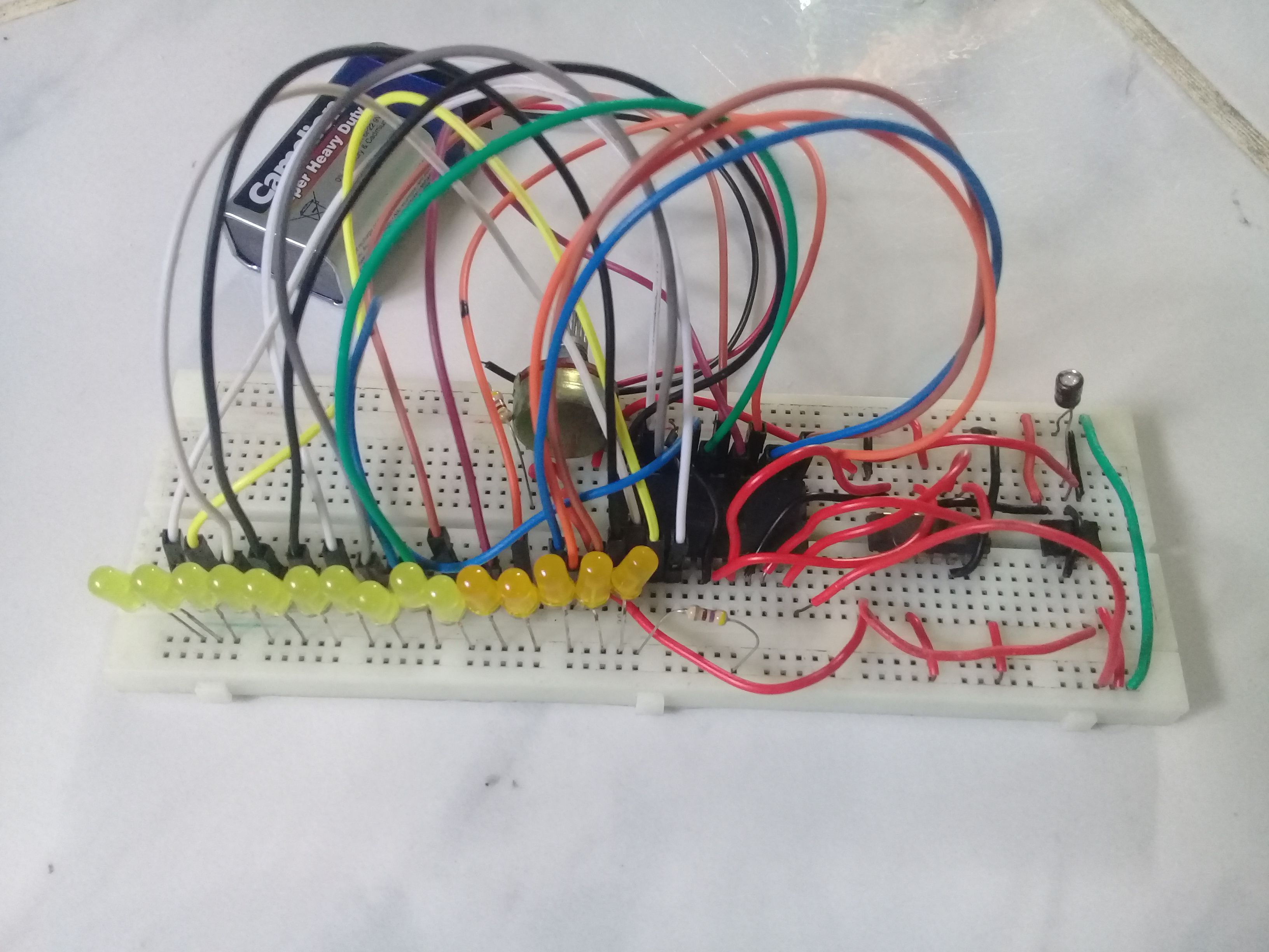
Actual Application
✔ Breadboard
✔ IC's
- 74LS193
- 74LS154
- 555 Timer
✔ Resistors (10k ohms and 220 ohms)
✔ Potentiometer (100k ohms)
✔ Capacitor (1 microF)
✔ Hook-up wire (#22)
✔ LED
✔ Battery (9V)
Software Application
✔ Proteus
Brief discussion of the following components:
Breadboard -- it is used for testing circuits before applyig to the real world. Or a device for temporary circuit making and designing.
IC (74LS193) -- It is an electronic components for UP/DOWN Binary counter. It has synchronous counting function.
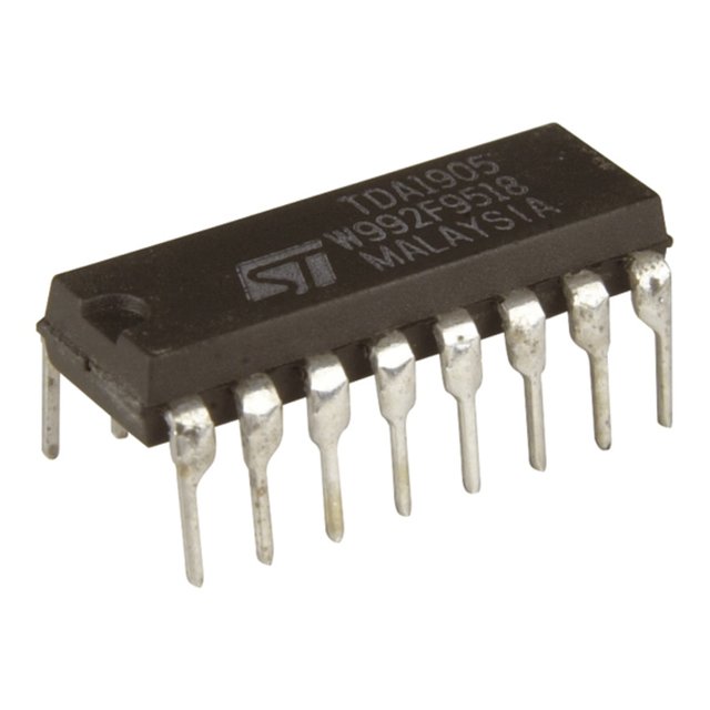
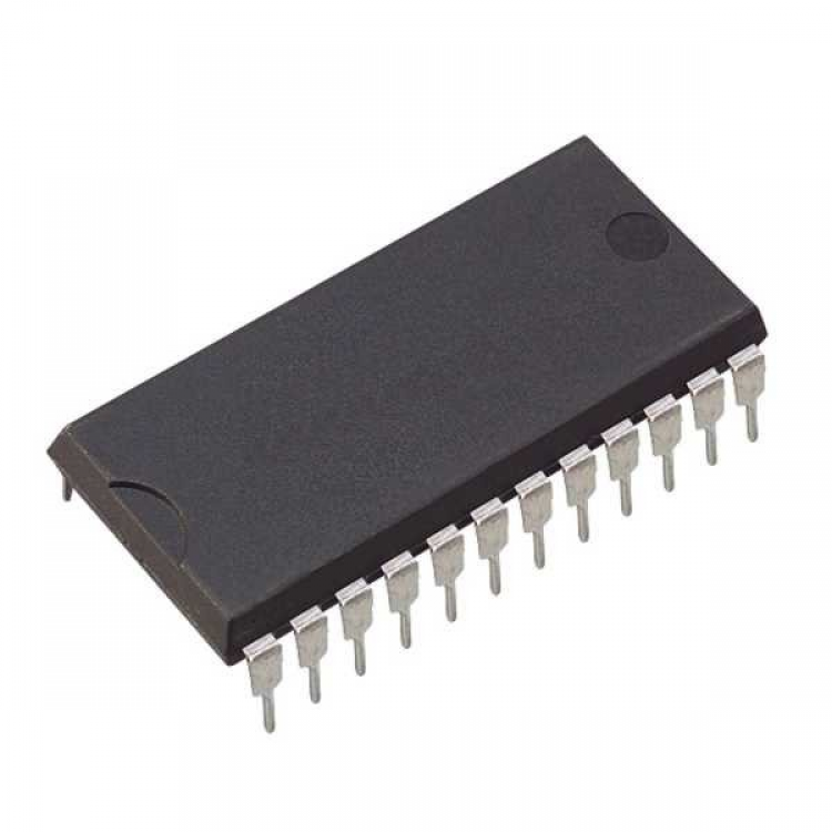
IC (74154) -- a 1 to 16 demultiplexer. It has 1 data input, 4 control or select input and 16 output. It has 24 pins all in all.
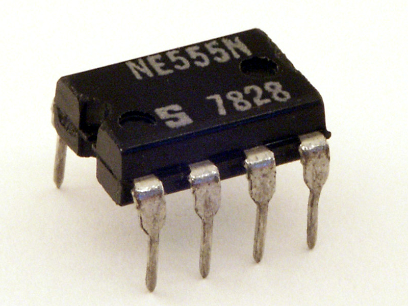
555 Timer-- a kind of IC which is use as oscillator, pulse generator and especially as timer.
Resistor -- is a passive component which has a electrical resistance as a circuit element.
Potentiometer -- a three-terminal resistor with a rotating contact used to adjust the voltage flow of the circuit.
Capacitor -- also a passive component which stores energy in the form of electrostatic field.
Hook-up wire -- used for low voltage and low current applications it is a single insulated conductor wire.
LED -- is a semiconductor device that emits light when activated. The process of electroluminescence happened as the elctrons combined with the electron.
Battery -- supplies the power of the circuits.
Pin Configuration of the Components Used
Potentiometer
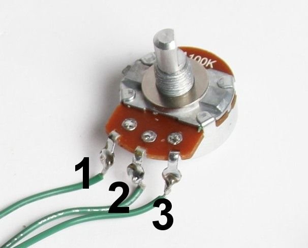
| Pin no. | Function |
|---|---|
| 1 | Ground |
| 2 | Output |
| 3 | Input |
555 Timer (IC)
| Pin no. | Function |
|---|---|
| 1 | Ground |
| 2 | Trigger |
| 3 | Output |
| 4 | Reset |
| 5 | Control Voltage |
| 6 | Threshold |
| 7 | Discharge |
| 8 | Vcc |
74LS193 (IC)
| Pin no. | Function |
|---|---|
| 1 | Input B |
| 2 | Output QB |
| 3 | Output QA |
| 4 | Down Clock |
| 5 | Up Clock |
| 6 | Output QC |
| 7 | Output QD |
| 8 | Ground |
| 9 | Input D |
| 10 | Input C |
| 11 | Preset |
| 12 | Carry Output |
| 13 | Borrow Output |
| 14 | Reset |
| 15 | Input A |
| 16 | Vcc |
74LS154 (IC)
| Pin no. | Function |
|---|---|
| 1 | Output |
| 2 | Output |
| 3 | Output |
| 4 | Output |
| 5 | Output |
| 6 | Output |
| 7 | Output |
| 8 | Output |
| 9 | Output |
| 10 | Output |
| 11 | Output |
| 12 | Ground |
| 13 | Output |
| 14 | Output |
| 15 | Output |
| 16 | Output |
| 17 | Output |
| 18 | Input |
| 19 | Input |
| 20 | Input |
| 21 | Input |
| 22 | Input |
| 23 | Input |
| 24 | Vcc |
Step by Step Process
Part I.
We will have first the designing of our circuit using the Proteus Software Application.
First thing to do is to open your proteus application to start designing your circuit, if you doesn't have a file for proteus click here and start downloading.

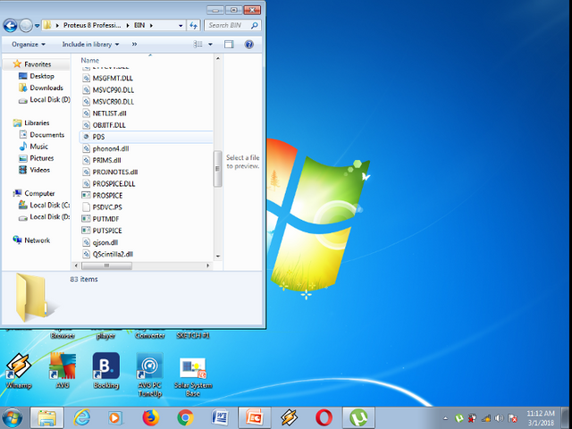
Now, after you finished to open the file, go to the BIN folder by clicking the icon.

Then find the PDS file for designing circuit diagram.
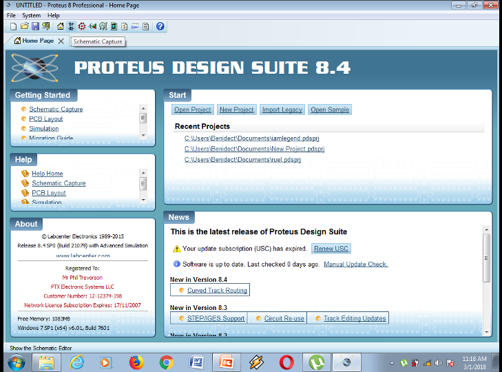
Then after clicking, you will come up with this area, now select the schematic capture located at the upper left of the ribbon tab.
Then you will be directly accessed to the designing area.
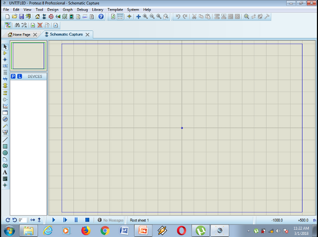
First thing to do is to gather all the components needed.
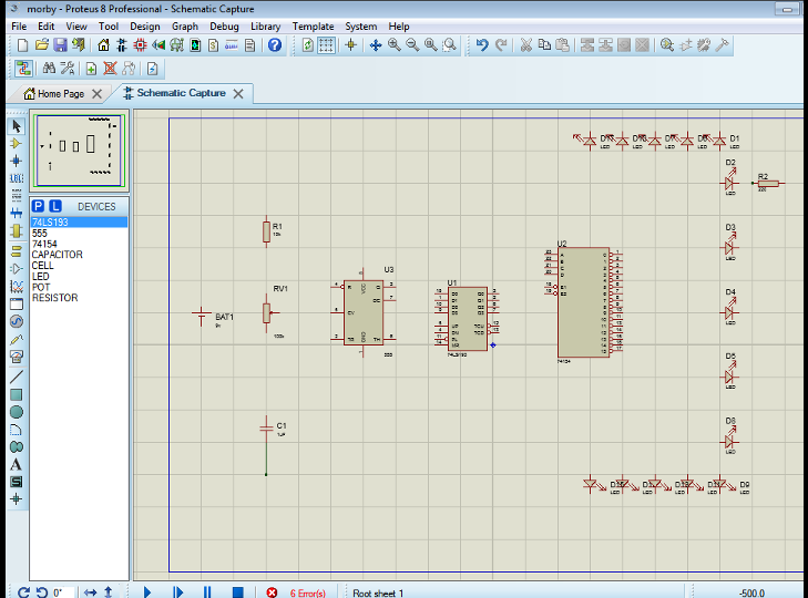
After gathering everything start your circuit designing.
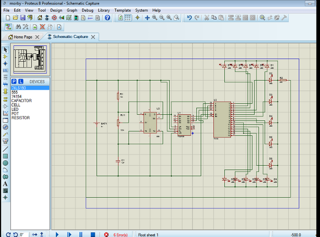
Part II.
Let's now move on to the actual application of our running led lights. First thing to do is to gather all the components needed and start constructing your circuit right away.
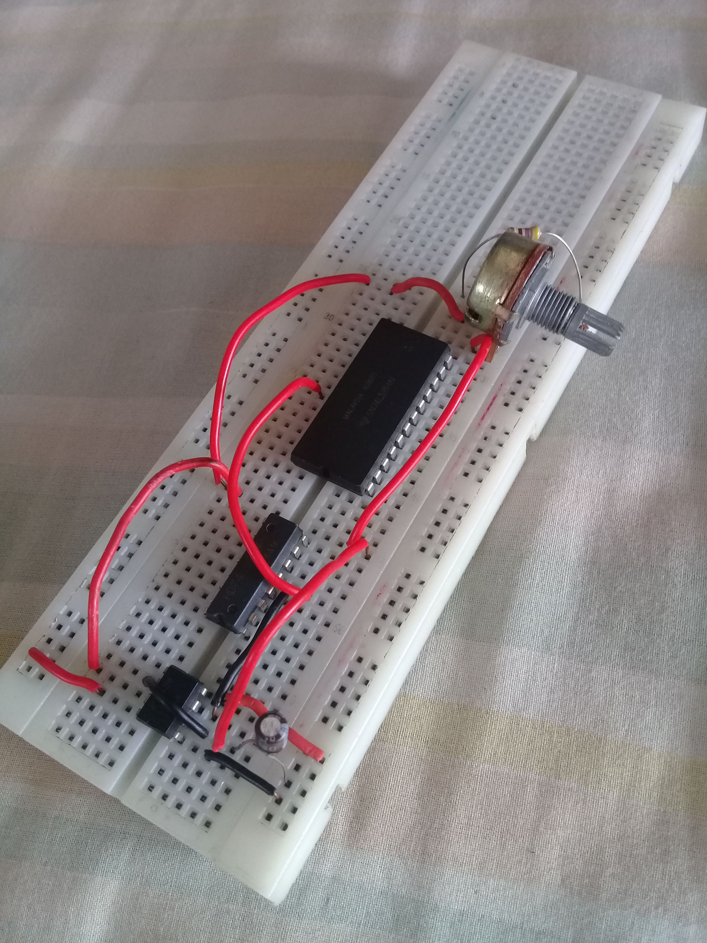
Then, after finishing in designing your circuit. Test it immediatly if it is functioning because based on my experienced, I got confused why does my circuit not operating well it is because of the improper placement of the components.
Part III.
Showing the activation of the circuit functionality by getting a video of the project.
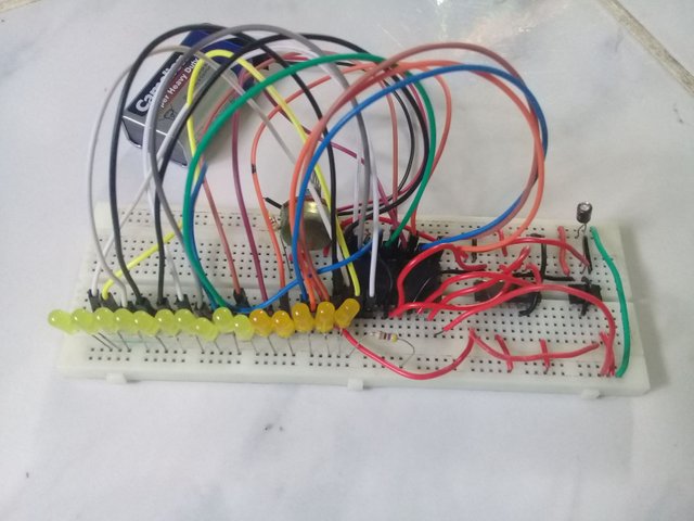
This is the example of RUNNING LIGHTS using LED. I first have it with 5 LED lights inorder to test if it functioned well.
Next is the final output of the project using 15 LED lights, though 74LS154 IC have 16 outputs I just ignored the 1 output because I only have 15 LED's in our house.
This video shows the actual adjustment of voltage flow in the circuit using potentiometer.
Additonal Attachment
I also have this video of mine showing the other design of forming LED's into word pattern. It was way back 3 weeks ago when I am making my project in Logic Circuit subject. The yellow lights were formed into a word as "ELECOMEN" simply means Electronics and Communication Engineering.
Overviewing the function of 555 timer
As what I've learn in school about electronics circuit construction, one common construction of circuit using 555 timer is the Astable Circuit. Astable Circuit is a circuit construction wherein the output voltage is periodic in pulse which alternates the VCC value and 0 volts. In this project, we used astable circuit as a signal input processed towards the demultiplexer inorder to come up with a running LED lights.
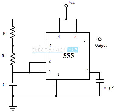
This is an example of a Astable Circuit Diagram.
Purpose of the Project Proposal
The ultimate purpose why I arrived in this kind of tutorial its because I want you to refresh your knowledge about making project using IC's. I'm not saying that digital technologies are worst to have but I just want you to encourage yourself to also automate a certain project involving the use of Integated Circuits.
This would be the first time that I post a tutorial about a project I made. I hope even for a little you gain knowledge and appreciated my work.
Congratulations! This post has been upvoted by SteemMakers. We are a community based project that aims to support makers and DIYers on the blockchain in every way possible. Find out more about us on our website: www.steemmakers.com.
If you like our work, please consider upvoting this comment to support the growth of our community. Thank you.
What is wrong with being dumb?