PART 1: BUILDING AN ANDROID PHONE CONTROLLED MOVING LED DISPLAY
Good day, good people on this great steemit community. Today, I will discuss about Scrolling Light Emitting Diode (LED) scrolling display. I will talk about building the device from the scratch using relatively cheap electrical components (some few resistors, capacitors, integrated circuits and a micro-controller). I shall also attach the circuit diagram, the software simulation, the printed circuit board design and the working code that has been debugged well enough to make the project work as intended.
The role of information dissemination in the society remains one which cannot be overemphasized. In addition to its vital functions of enlightening, educating, entertaining, facilitation of commercial activities through advertisement, marketing of goods and services, its use in surveillance, monitoring (security, traffic control) and description of places also remains indispensable.
Various means of information dissemination which include broadcasting (radio and television), the internet, newspaper, bill boards, sign posts and neon displays, are employed, the choice of which depends on factors such as the targeted audience, the environment concerned, the purpose, available technology and economy. However, regardless of the medium employed, of utmost importance is the fulfillment of the purpose of information dissemination. The information should also be relevant in terms of reaching the intended range of audience with clarity, objectiveness and a good degree of comprehension. Also, response to the information is further enhanced when the medium employed is attractive and highly inviting, as the case for a moving display.
This project work involves the design and construction of scrolling (moving) advert display. A moving message display which could also be referred to as an electronic notice board is an electronic gadget that is capable of displaying lengths of alphanumeric characters, symbols and any form of representation on a matrix (array) of light emitting diodes (LEDs) scrolling the characters across the screen for reading the emerging information. It has an unparalleled advantage in drawing people’s attention by prompting them to reflect many times on the scrolling lights automatically displaying either messages of advertisement, place description or greetings at any time of the day. It can be used for both indoor and outdoor purposes. In fact it is the most alluring, unique, captivating and attractive means of information dissemination.
The moving message display can be realized in different ways with operational possibilities achievable varying accordingly with the design. This design features an android application-enabled user interface with Bluetooth connectivity with which the user can input or edit data to be displayed.
The digital scrolling light advert display would be implemented using Light Emitting Diodes (LED) matrix array. The LED matrix array would be driven by a micro-controller programmed to handle the character/ message display. The choice of the LED matrix array and the use of a micro-controller are to ensure that the display unit does not consume much power. This design features an android application-enabled user interface with Bluetooth connectivity with which the user can input or edit data to be displayed.
SYSTEMS DESIGN
Here, I will explain in details the components, parts and design consideration needed in building the moving led display, and how they can be interfaced with the arduino micro-controller.The entire design comprises five major stages namely: LEDs array stage, power supply stage, shift registers stage, micro-controller stage and the serial communication (Bluetooth) stage .
LEDs ARRAY STAGE
Components/ Equipment needed and Quantities:
- 100cmx10cm Perspex board (1).
- A large amount of Light Emitting Diodes of any color orientation aside white.
- 100cm x1cm Copper board (7)
- Soldering Lead and Soldering LED.
-hand drilling machine - Flexible wires.
Light Emitting Diode
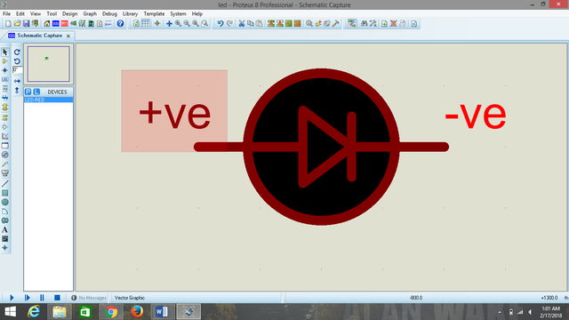
A light emitting diode (LED) is a semiconductor diode that emits light when an electric current is applied in the forward direction of the device, as in the simple LED circuit.
They are used as indicator lights in ultra-power applications such area lightings and in flashlights. There are varieties of LEDs, in terms of the emitted light color. This emitted light of LEDs depends on the material it is made from (we have some made from Gallium phosphide, some from Gallium Arsenide and some others from Gallium Arsenide Phosphate).
In terms of the emitted light visibility, LEDs are classified into Visible (those whose lights, one can see) and Infrared LEDs (those whose lights can’t be viewed with naked eyes, but can be seen under a camera). LED has two legs known technically as terminals. The longer of the two terminals is the Anode (positive) and it’s the terminal with the shaded portion as shown by the electrical symbol. The shorter leg represents the cathode (negative terminal).
LED: looking through the inside of it, big head denotes cathode.

Source
LED electrical symbol
.png)
Credit : drew by me (@thestronics) using proteus software
How to design a LED array
The least LED array comprises 56 LEDS in total. The array is made arrived at by arranging LEDS in 8 columns and in 7 rows (8x7). To design a more lengthy scrolling display, the number of columns is increased by a factor of 8. So, we can have a (16x7), (24x7), and (32x7) arrangements and so on.
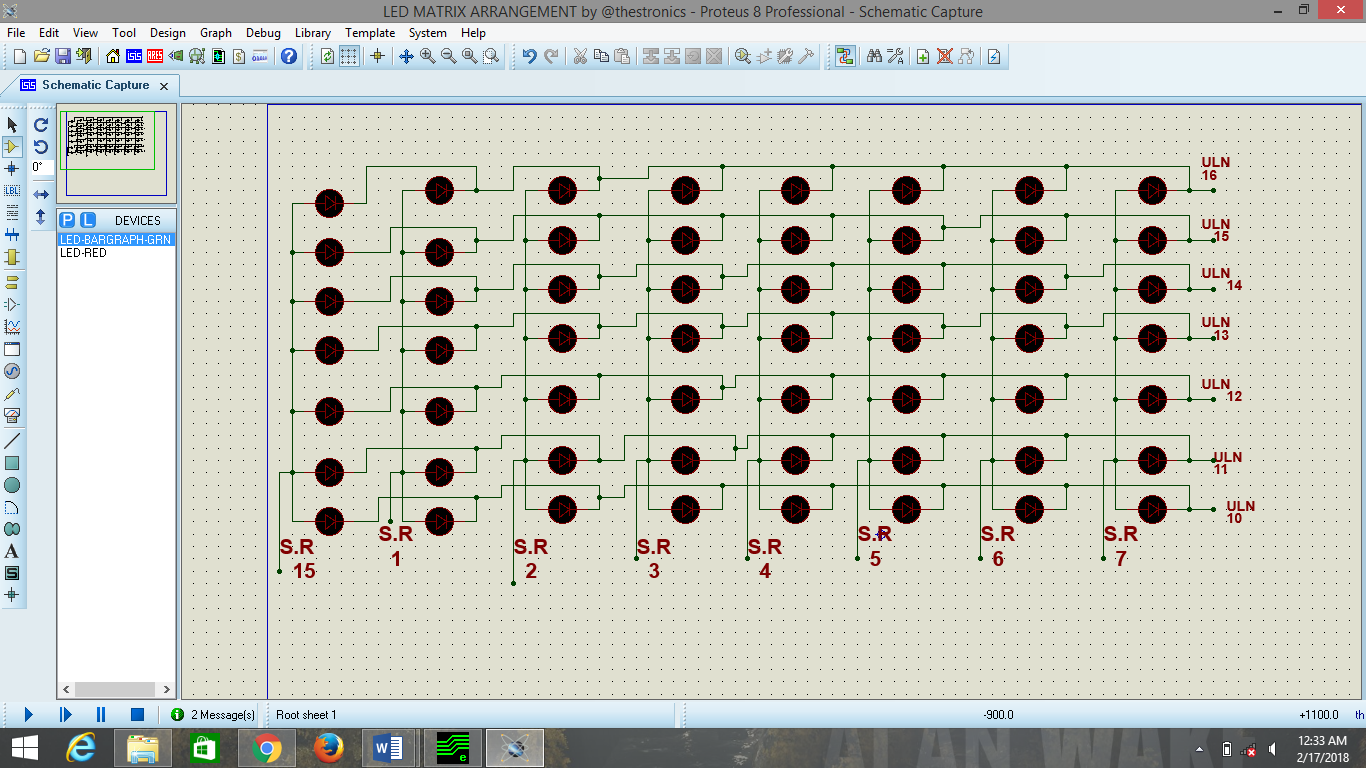
All the anodes (positive terminals) in the first column are connected together and with a flexible wire to pin 15 of the Shift register (74HC595) integrated circuit denoted by S.R in the diagram shown below. All the anodes in the second column are joined together to pin 1 of the S.R, third column anodes to pin 2 of the S.R. This is done for up to the last (eight column) which is connected to pin 7 of the shift register, S.R.
LED Matrix circuit diagram
.png)
credit: drew by me (@thestronics) using proteus software
As for cathodes, they are connected along the row as shown above (the cathodes are placed on a copper board to ensure continuity of the terminals). Row 1 is connected to pin 16 of ULN2003 integrated circuit, row 2 to pin 15, row 3 to pin 14, row 4 to pin 13, row 5 to pin 12, row 6 to pin 11 and row 7 to pin 10 of the ULN2003.
If it’s for a (16x7) arrangement, the same procedures stated above are taken for the first eight columns. But for the 9th column to the 16th column, the steps are repeated (9th to pin 15, 10th to pin 1, 11th to pin 2…..16th to pin 7). This same step is repeated for scrolling displays with a very long column e.g. 64x7 which I would explain in deep in my next write up.
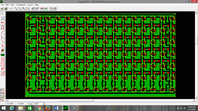
After the arrangement of the LEDs comes its printed circuit board design. It is this printed circuit board made that would be placed on the perspex, where holes (to contain LEDs terminals) are drilled using a hand drilling machine. The terminals of the LEDs are then soldered with a soldering iron and LED as stated and indicated in the LED array diagram drawn above.
LED Matrix printed circuit board
.png)
credit: drew by me (@thestronics) using Express PCB software

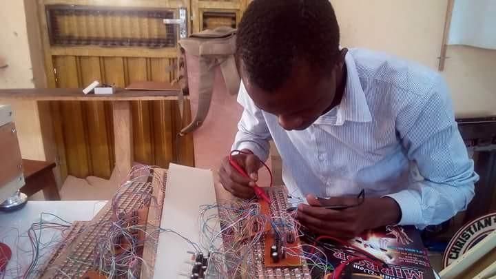
@thestronics checking any possible errors on the LEDs array soldered on a perspex
THANKS FOR READING!!!
References
embedded-lab


Being A SteemStem Member