HOW EXACTLY DO WE MEASURE ELECTRICITY WITHOUT TOUCHING OR SEEING IT
Before now, I began to wonder how electricity/ electrical quantities were measured to determine its actual magnitude, during my WAEC many years back, was the first time I handled an electrical measuring instrument.
Though not the last, it seemed like magic how that at the application of pins to both ends of a battery, there was a positive deflection but if for one reason or the other, the polarity was altered, there came a negative deflection.
I began to wonder the science principle or the force which made the pointer move from zero and end at a point which we agreed was the value. To measure height, it can be easily calliberated and quantied, same with mass but...
But how do we quantify a physical quantity that cannot be seen?
To measure the unseen, we have to understand the nature of the unseen. Not only do we need to understand its nature, but more importantly, we need to understand its characteristics, some of the principles of electricity taken advantage of in electrical measurements is the principle of attraction and repulsion, electro mechanism, Electromagnetic Induction, etc.
The principle via which any electrical instrument will therefore base itself would be the major determinant of the design of the system.

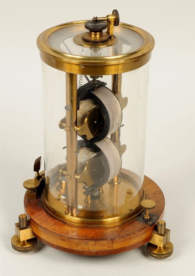
A voltmeter (an electric meter) From pxhere.com CCO license
Most electrical instruments needs operates by allowing a torque called the deflecting torque to act on its indicator on the application of the operating current. These deflecting instruments can be in 3 forms
Indicating Instruments: As the word implies, it indicates the magnitude of the quantities to be measured, that ammeter I told you I used during high-school, well that’s a good example of an indicating instrument, it has dials moving on a graduated dials.
The Integrating Instrument: What these instrument simply does is to summate the total magnitude of electrical quantities indicated over a period of time, have you ever wondered how your prepaid energy meter works and operates, thats just a perfect example of one.
Recording Instrument: These instrument is basically used to record electrical values at certain conditions of the applied load to it.
Let’s now base our interaction today on how the indicating instruments work and operates, as it would lay a foundation on our further interactions about how energy meters work.
3 basic TORQUES
For successful and accurate measurements to take place there are 3 basic torques that must come to play one which we have already discussed but we will throw more light on.
- The deflecting Torque (Operating Torque component): This torque is brought about by an action of the operating component on the device (Of course the currents action to provide torque is not automatic, but dependent on the design of the Instrument in question).
In essence the deflecting torque causes the Instrument to move from its Zero level. It is denoted as Td
- The Controlling Torque (Restoration torque Component): After deflecting torque is in action, one question we need to ask ourselves is this. Newton First law of motion tells us that a body would remain in continuous rest or motion except it is acted on by an external force right? So if the deflection Torque causes the indicator/pointer to go from Zero level.
The Control Torque is that equal but and opposite Torque that would bring the Indicator to rest at a point in the calibration where the torque equals the deflection torque.
It is denoted Tc Not only that, but the control Torque would bring the indicator back tomits zero position immediately the action causing the deflection torque is removed.
Examples of mechanism is responsible for the Provision of Tc includes the Spring control and the gravity control; For the spring control (which is the commonest means used) Attatching a spiral non magnetic hair spring to the moving system would do the trick, for the gravity controlled instrument, a small weight is attatched to the bottom of the indicator.
- The Damping Torque :
Think of throwing a ball to a cemented ground or a smooth surface, sure the ball wouldn’t just stay on the floor, it would rebound and hence an oscillatory effect is seen.
Let’s look at it this way; The force that made our ball to fall to the ground is our deflection torque, the reaction from the ground which was meant to bring the ball to rest on hitting the ground is the control torque, but you see, that is not instant, the ball would still undergo a period of time of rebounding before coming to its steady state.
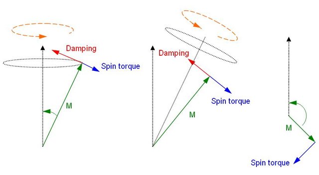
Except there is another force in place to expedite these timing, this torque is known as the Damping Torque.
If the instrument is not accurately damped, there are two disadvantages; If it is overdamped it would offer high resistance during motion or rest, hence making the meter to be slow, if its however underdamped, the pointer would oscillate around its fixed point for a long period of time before coming to rest.
Damping : Wikimedia Commons under CCASA 3.0
Methods of damping an instrument include, Air damping, Fluid damping or eddy current damping. The air damping occurs due to air friction, by attaching an aluminum piston to our pointer, a cushioning effect is provided by air which in turn prevents the pointer from oscillating about its fixed point.
The fluid friction is not so frequently used due to the fact that most instruments are movable. Therefore a high tendency occurs that leakage of the liquid material (usually oil) during fluid damping might occur.
SOME DESIGN METHODS OF INDICATING INSTRUMENT
The major difference between the magnitude and nature of current and voltage measured by Indicating Ammeters and Voltmeters depends greatly on the design and operational method of the instrument.
For instance, certain instruments are designed to measure dc only while others are constructed to measure ac only well so we have the ability to measure both. Some of these instrument types which would be discussed shortly are
PMMC (DC only)
Dynamometer (AC and DC)
PERMANENT MOVING MAGNETIC COIL INSTRUMENT (PMMCI)
Its principle of operation is simple. When a coil carrying current is in a magnetic field, the coil will experience a force perpendicular to the direction of the current flow in the coil. The magnitude of this force is proportional to the current by the relation
F=BILN
Where B is the field
I is the current
N is he number of turns of the coil
And L is the length of the conductor,
But In the design of the instrument, all we need to know is that F is proportional to I.
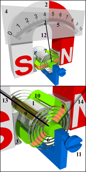
The PMMC basically comprise a light rectangular coil of many turns (as the turns increases the force), the coil is mounted between magnetic poles (usually permanent magnet), current is led into the coil by two hair coil springs which also provides the controlling torque. A pointer is then attached to the moving system placed between the coil.
When operating current is applied to the instrument to measure either current or voltage, it first passes through the hair springs to the coil of the instrument, the coil being placed between the two magnetic poles, the field created. A mechanical force (Deflecting torque) is therefore generated and made to move the pointer.
PMMC cannot measure ac simply because, AC comprise both positive and negative current and voltage cycle, while the PMMC would give a positive reading in its positive half cycle, it would not do the same at negative half cycle rather there would be something called ”current reversals” this makes the pointer move in the other direction (-ve direction). The controlling torque is produced by the spiral spring. Current induced by the permanent magnet in the device is provides eddy current which is used to generate the DAMPING TORQUE.
THE DYNAMOMETER
By design and principle of operation it can be used to measure both ac and dc, which is of course one improvement to the PMMC instrument. It operates on the principle that mechanical force exist between 2 current carrying coils. Don’t mix it up with PMMCI, the mechanical force in PMMCI is generated by a coil and a magnetic field but for the dynamometer, its more about 2 coils only.
To design an instrument with these operational principle, what we need is simple, we need 2 coils and a means through which current enter into it, we must take into consideration the moving system through which the pointer would move to indicate the magnitude of operating current.
The 2 coils are designed such that one is fixed and the other is movable, the fixed coil is divided into two equal parts and connected in parallel to each other, the moving coil is connected between the fixed coils and like the PMMC the current is led into the material through hair springs which also provides the control torque. And the damping torque is produced by air friction.
When operating current flows through the hair springs, it flows into the moving coil which in turn causes the pointer attached to it to move, as discussed earlier, it would come to rest at a point in the calibration where the deflecting torque equals the controlling torque (Td=Tc).
By reversing the current, the polarity of the Fixed coil current is also reversed. Therefore, it indicates the same value of current or voltage. In both positive and negative cycles. It is for this reason that the Dynamometer can be used to measure both AC and DC.
AMMETERS AND VOLTMETER MEASUREMENTS
You might begin to wonder why all through the write-up we didn’t treat ammeter and voltmeter with specialty, here is the reason!!!
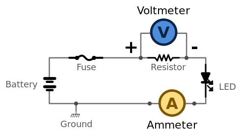
The difference between an ammeter and voltmeter is not in the design of the indicating instrument but in the method of connection of these device to the load circuit. An ammeter is connected in series to the load such that the same current flowing into the load would flow into the instrument and an exact value f the current would be measured this phenomenon is called ”ammeter loading”
However, the voltmeter is connected in parallel (across the load) to the load whose voltage is to be measured, consequently, a current that is proportional to the voltage would flow into the instrument and give a value of the voltage.
CONCLUSION
We can now see that measuring the magnitude of electrical quantities lies in understanding its nature and principles and then creating a design such as can take the magnitude of the quantity to be measured and causing a proportionate deflection over its calibration.
REFERENCES
For Further study and understanding, you might want to check out the following;
https://circuitglobe.com/classification-of-measuring-instruments.html
https://sites.google.com/site/electricalmeasurements4u/home/classification-of-measuring-instruments
http://engineeringwrittennotes.blogspot.com/2016/07/dynammeter-type-instruments-engineering.html?m=1
https://www.yourelectricalguide.com/2017/01/deflecting-controlling-damping-torque
If you write STEM (Science, Technology, Engineering, and Mathematics) related posts, consider joining #steemSTEM on steemit chat or discord here. If you are from Nigeria, you may want to include the #stemng tag in your post. You can visit this blog by @stemng for more details.

You can also join us at Promo-Mentors, to improve your blogging skills. Join our discord channel and meet awesome mentors who are willing and ready to shape your writing skills.

Congratulations @lawkay! You have completed the following achievement on the Steem blockchain and have been rewarded with new badge(s) :
Click here to view your Board of Honor
If you no longer want to receive notifications, reply to this comment with the word
STOPDo not miss the last post from @steemitboard:
Hello! I find your post valuable for the wafrica community! Thanks for the great post! We encourage and support quality contents and projects from the West African region.
Do you have a suggestion, concern or want to appear as a guest author on WAfrica, join our discord server and discuss with a member of our curation team.
Don't forget to join us every Sunday by 20:30GMT for our Sunday WAFRO party on our discord channel. Thank you.
I think this:
Is better written as:
Also, I think the measuring instrument of choice in this article is primarily that of analogue systems and not digital. Interesting article. Thank you for sharing it with us.
Yes Of course, analog instruments was primarily covered here because it operates on basic electrical principles.
However in my next post on Energy meters, I would be touching digital measuring systems a little, my research on it was quite interesting and I ll like to share!!!
This post has been voted on by the SteemSTEM curation team and voting trail in collaboration with @curie.
If you appreciate the work we are doing then consider voting both projects for witness by selecting stem.witness and curie!
For additional information please join us on the SteemSTEM discord and to get to know the rest of the community!