Per Unit System of Representation: A Way to Collapse Power System Voltages to a Single Voltage Level.
Per-Unit System of Representation
Power transmission lines are operated at voltage levels where kilovolt(KV) predominates and thus is the most convenient unit to express voltage. Because of large amount of power transmitted, Kilowatts or megawatts and kilovoltamperes or megavoltamperes are the common terms.
Power system computations can be made by taking either the actual values of different quantities or expressed as a percent or per unit of a base or reference value specified for each.
If we opt for the actual values of voltage, current, volt-ampere and impedance, it therefore means that as we move along the line of power system having several different voltage levels, we must find a way of transforming all impedances to a single voltage level.
Fortunately, power system engineers have seen through all the difficulties such as transformation of all impedances to a single voltage level, and decided to come up with the per-unit system such that various physical quantities such as power, voltage, current and impedance are expressed as decimal, fraction or multiples of base quantities.
By adopting the per-unit system of representation, the different voltage levels in the line of the power system collapses, and a power network involving generators, transformers, and lines (of different voltage levels) reduces to a system of simple impedances.
The per-unit value of a quantity is the ratio of the actual value of that quantity to an arbitrary chosen value of that quantity.
The arbitrarily selected value is known as the base value. Both the actual value and the base value are expressed in the same unit so that the per-unit value comes out with no dimension.
The base values are generally indicated by a subscript b and per-unit value by subscript p.u.
Thus, per unit system of any quantity can be defined as:
Quantity in per unit= (actual quantity)/(base value of quantity)
There is a relation between these quantities, viz: kilovoltamperes(KVA), Kilovolt (KV), current (I) and impedance (Z). Out of the four quantities mentioned above, only two are independent. Once the independent variables amongst the four are defined, the other ones can easily be calculated from the knowledge of the independent variables.
Voltage, current, kilovoltamperes and impedance are so related that selection of base values for any two of them determines the base values of the remaining two.
It is convenient to select the base values of KVA and KV, and calculate the base values of current and impedance from the selected base KVA and KV.
In a three phase system, the base values can be selected to be 3-phase KVA and line-to-line KV.
The base impedance is that impedance which will have a voltage drop across it equal to the base voltage when the current flowing in the impedance is equal to the base value of the current.
The base kilovoltamperes in single-phase systems is the product of base voltage in kilovolts and base current in amperes.
Most often, base mega-voltamperes and base voltage in kilovolts are the quantities selected to specify the base.
.png)
For single-phase systems, or three phase systems where the term current refers to line current, where the term voltage refers to voltage to neutral and where the term kilovoltamperes per phase, the following formulas relate the various quantities:
Base current, A= (base KVA(1ϕ))/(base voltage,KV(LN))….(1)
Base impedance, Ω= (base voltage, V(LN))/(base current, A)….(2)
But from equation (1), base current has been defined and we can substitute the value in equation(2)
So that Base impedance=(base voltage, V(LN))/((base KVA(1ϕ))/(base voltage, KV(LN)))
Base impedance = base voltage, V(LN)× (base voltage, KV(LN))/(base KVA(1ϕ))….(3)
The prefix K stand for kilo and has equivalent value of 1000. When you multiply K to a quantity, you must divide the quantity by 1000 because by multiplying by K, you have multiplied the quantity by 100 and as such, you must divide by 1000 to counteract the K.
From equation (3) above, we can manipulate it to give us a form which we can easily use in solving problems.
(base voltage, V(LN) ×base voltage, V(LN))×1000/(base KVA(1ϕ))
[(1000×base voltage,(VLN)2)/(base KVA(1ϕ))]×1000/1000
(base voltage,(VLN)2×10⁶)/(base KVA(1ϕ)×103)
(base voltage,(VLN)2×(103)2/(base KVA(1ϕ)×103)......(4)
(base voltage,(VLN)2×(K2)/(base MVA/1000(1ϕ)×1000)......(5)
= (base voltage,(KVLN)2/(base MVA/1000(1ϕ)).......(6)
From equation (4), you will notice that the denominator containing base KVA(1ϕ) changed to MVA(1ϕ) in equation (5) . This is because when you multiply K by K, it will give you mega which is denoted by M. Just like before when you multiply any quantity with K, you must divide by 1000'
In these equation 1ϕ and LN deotes ''per phase'' and ''Line to neutral'' respectively. If the above equation are used for a single-phase circuit, KVLN means the voltage across a single phase line
The base voltage to neutral is the base voltage from line to line divided by √3 .
Similarly, the three phase kilovoltamperes is three times the kilovoltamperes per phase, and the three phase kilovoltamperes base is three times the base kilovoltamperes per phase.
It then means that the per unit value of three phase kilovoltamperes on the three phase kilovoltampere base is identical to the per unit value of the kilovoltamperes per phase on the kilovoltamperes per phasebase. The three phase circuit are usually analysed using their equivalent value in per phase value (single phase).
Since the base values are three phase KVA and line to line KV, confusion may arise as to the validity of the relation between per unit value of line to line voltage and the per unit value of the line to neutral voltage. It is worthy to note that the p.u. value of the line to neutral voltage on line to neutral base is equal to the p.u. value of line to line voltage on line to line voltage base. Also the p. u. value of total 3-phase KVA on 3-phase KVA base is equal to the p.u. value of KVA per phase on KVA per phase value.
A numerical example will clarify the relationships concerning the above observation.
Let 3-phase base KVA be 90,0000KVA
Line to line base KV = 240V
Then one phase base KVA= 90000/3 =30,000KVA
Line to neutral base KV = 240KV/√3 = 138.57KV
If actual three phase KVA is 60000KVA (so that the per phase value is 20000KVA) and line to line KV is 190KV (so that the actual line to neutral voltage in KV is 190KV/√3 = 109.7KV)
thus, p.u. KVA(3ϕ) = 6000/90000 = 0.67
p.u. KVA(1ϕ) = 20000/30000 = 0.67
p.u. KVA(3ϕ) = p.u. KVA(1ϕ) =0.67
p.u. KV(3ϕ) = 190KV/240KV = 0.7917
p.u. KV(1ϕ) = 109.7KV/138.571KV = 0.7917
Per Unit Impedance Of Transformers
In circuits containing transformers, the base volt-ampere or KVA is the same on both sides of the transformer but the voltage base is dictated by the voltage transformation ratio of the transformer. This selecttion equalises the p.u. impedance on both sides of the transformer.
.png)
To illustrate the above point, let us consider a single phase transformer having Vp and Vs as the primary and secondary voltages and Ip and IS as primary and secondary currents.
Let the impedance as referred to the primary be Zp
Then, Vp/Vs = Is/Is
Base Volt-ampere= VpIp= VsIs
Base voltage is Vp for primary and Vs for secondary
Base impedance for primary = Vp/Ip
P.u impedance as referred to the primary = Zp/(Vp/Ip) = (IpZp)/Vp
Actual impedance as referred to secondary = Zp/(Vp/Vs)2
Base impedance for secondary= Vs/Is
P.u impedance as referred to the secondary = actual impedance of secondary/base impedance of secondary
=Zp/(Vp/Vs)2/(Vs/Is)
=Zp× (Vs)2/Vs)2) × Is/Vs
= (ZpVsIs)/(Vp)2
But VpIp = VsIs
Thus, (ZpVsIs)/(Vp)2=(ZpVpIs)/(Vp)2=P.u impedeance as referred
This shows that the voltage transformation ratio of the transformer equalises the p.u impedance on both sides of the transformer.
The load power at its rated voltage can be expressed by a per unit impedance. If SL(3ϕ) is the complex load power, the load current per phase at the phase voltage Vp is given by:
SL(3ϕ) = 3Vp(Ip)*
where Vp is the phase value of voltage and (Ip)* is the conjugate of the phase current.
The phase current written in terms of the ohmic load impedance is Vp/Zp
Zp = (3|Vp|2)/(SL(3ϕ))
The load impedance in per-unit is Zp.u = Zp/ZB =
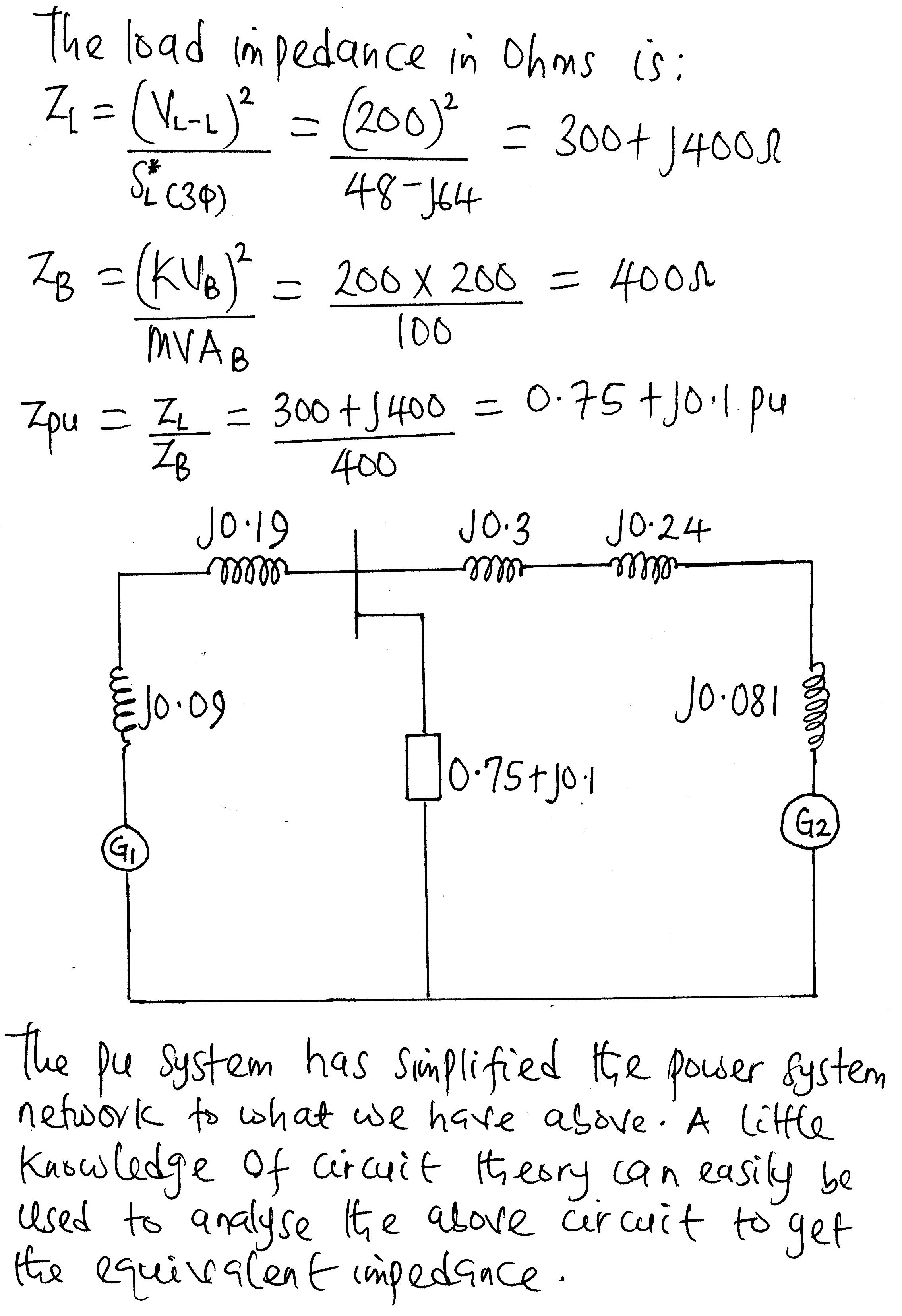
Zp = (|VL-L|2)/(SL(3ϕ))
The load impedance in per-unit is Zp.u = Zp/ZB = |(VL-L/VB)|2 × (SB)/(SL(3ϕ))*
where ZB is the base impedance and Zp is the actual value of the impedance.
Zp.u = (|Vp.u|2)/(SL(p.u))*
Often times the per-unit values are given for a specific base kV, but the problem being solved is using a different base.It may then be necessary to transform the per unit value to that of the new base using the the relation below:
Per Unit impedance referred to new base = [Per unit impedance referred to old base][Base KVold/Base KVnew]2[Base KVAnew/Base KVAold]


Advantages Of Per Unit System Of Representation
Power system contains large number of transformers and as such, analysis of power system will entail referring impedances to the secondary or to the primary which is not equal on both sides of the transformer. Therefore, it makes computations rigorous.Fortunately, if we select the base value properly, the per unit impedance is the same on both sides of the transformer.
Per unit value representation gives a more meaningful and easily correlated data.
It reduces the chances of mix-up betweenphase and line voltages, single phase amd three phase powers and in the case of transformer between primary and secondary voltages.
Conclusion
In power system studies such as in fault analysis and computation, different power system eqipments and machines with different ratings are often linked in the line of power system and as tyou move along the line there exists diffeent voltages. The different voltages are as a result of step-up and step-down transformers involved in transmission and distribution.Due to this different voltage levels, there woulb be need to refer the impedances of the transformers either from the primary side or to the secondary side which is time consuming and prone to errors.
The more practical way to circumvent this challenge is to choose a common base value for current and voltage to which we can refer the actual values.This approach will reduce the power system network to a system of impedances or reactances which we can analyse using our knowledge of circuit theory.
The realisation of system of impedancess is of vital importance in fault calculations bearing in mind that the fault current is limited by impedance up to the point of fault.
Being A SteemStem Member
Awesome. Per unit value system is paramount in power system, especially in fault analysis where the of variables are widely spread. Thanks for sharing.
You are right about its importance in fault analysis where the power system is reduced to a simple network of impedance without any recourse to voltage levels. Thanks for your time.
Very good information! thank you.