Arrangement of Loads in a Circuit: Series and Parallel Connection
We started from the basics of electricity and the concept of atom and electron flow. The flow of electron is the charge, and if there is no flow of charge, I do not think we can venture any further into this discussion. We also talked about circuits which constitute any number of elements joined at terminal points, affording at least one closed path through which current can flow.

Life is hardly simple, and this translates to everything in the world even with electrical technology. A simple circuit with a single source and a single load seldom exist except such devices like battery torches. We will consider systems with loads that exceeds one.
There are different ways in which elements can be arranged in a circuit. They can be arranged in series, in parallel or some cases the elements may neither be in series or parallel. We will look at the different ways of the arrangement of elements in a circuit starting from the series arrangement. It is rather unfortunate that we have to rely on equations sometimes to do some illustrations, but that does not take anything away from the underlying concepts.
In the resolution of any circuit problem, one must be conversant with Ohm’s law, Coulomb’s law, Faraday’s law, and Kirchhoff’s law. I will not bother my readers much with all these laws at the same time, but we will elicit the help of Ohm's law almost immediately.
To handle two or more loads, one needs to be proficient in spotting series-connected loads and parallel-connected loads. This skill is enhanced by constant practice involving different arrangements and trying more problems until we develop the skill in our finger-tip
Series Connected Elements
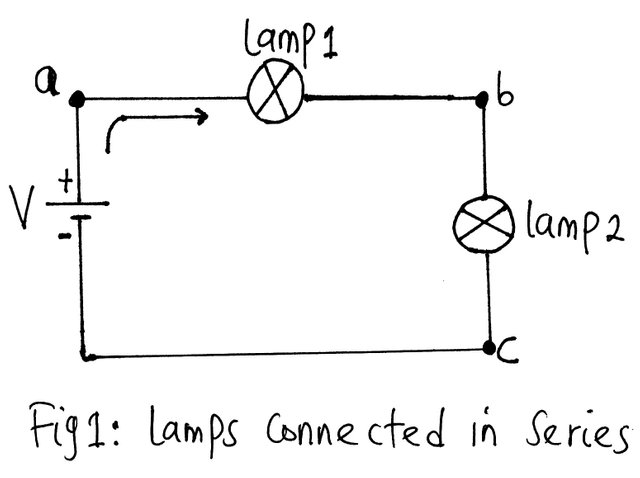)
Two elements are said to be in series if only one point is common to them that is not linked to any other current-carrying elements of the network.
Consider the circuit of the figure above consisting of two lamps: lamp 1 and lamp 2. Lamp 1 and lamp 2 are in series because they have only point b in common. The other end of the lamps is connected elsewhere in the circuit. The same reason goes for battery E and lamp 1 for having terminal a in common. Since all the elements of the circuit of the figure above are in series, the network is called a series circuit.
)
Some practical example of a series circuit includes joining of pipes to get water from a water source, holding hands together to form a circle, tying of small pieces of rope together to form a long rope.
In a series circuit, the same current runs through all the elements in the circuit.
We are already aware that resistors produce heat when passing current and we will explore this phenomenon deeply.
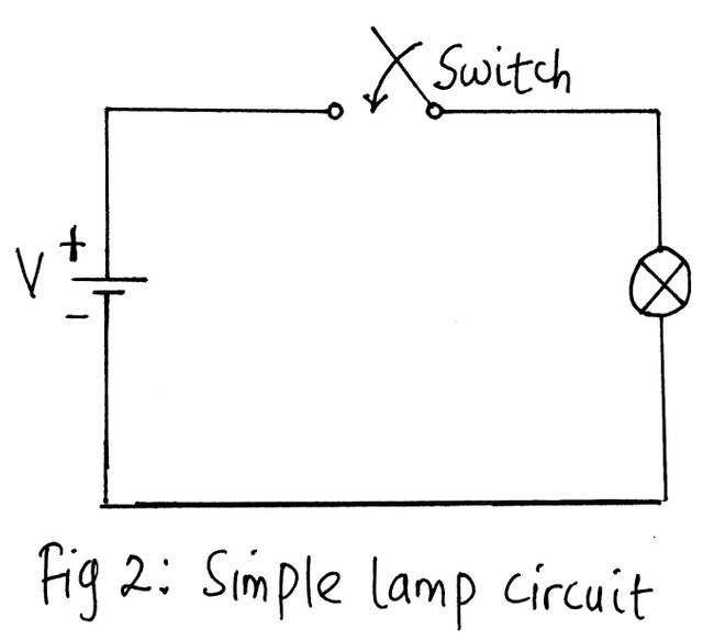
Let us consider what will happen in the circuit of the figure 2 above containing the load unit of a lamp bulb and a dc source.
In real life, we might observe that the light output is not bright enough and decide to add a second lamp as shown in figure 3 below:
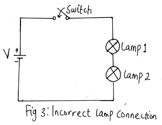)
At first glance at the circuit, it would seem as if it would work satisfactorily judging from the fact that the same current that powered the initial first lamp will move and passes on to the second lamp. But it will surprise you that upon switching the circuit to the supply, both lamps will give out very little light.
What did we do wrong?
We have already established that the passing of a current through the lamp filament wire can make it so hot that it gives out a light. This will only occur if there is enough current to raise the temperature of the filament 30000C. But if the current is insufficient, it would result in a dim glow from the filament because the temperature did not get up to 30000C. This insufficient current is what happened in the circuit of fig 3 above.
)
Now, the question is- why is the sudden reduction of current if there is no diversion of current?
In the circuit of fig 2, notice that the lamp operated at its normal brightness by making use of a specific level of current. And we already know that voltage is the driving force of electrons that make up a Coulomb of charge at 6.242 × 10¹⁸ electrons are made to pass through an imaginary plane for a minute.
In line with this argument, we may say it was the voltage and the resistance of the filament that was responsible for the flow of electrons and hence the current through the lamp filament. The voltage drop across the filament in the first instance (fig 2) is equal to the applied voltage.
)
Do we now say that with the introduction of the second lamp, that there would not be any voltage remaining to push the electrons to flow through the second lamp?
In a complete circuit, the above assertion cannot hold true because it is not practically feasible for the current to flow in one part of the circuit and not the remaining part.
There must be a way out, in the sense that the first lamp shares the voltage with the second lamp with direct relation to the magnitude of the resistance of the filament. That is, the first lamp utilizes less of the supply voltage and leaves some for the second lamp. If the first lamp was to have a higher resistive filament, more voltage drop will be experienced across the resistor and leaves up the remaining voltage for the second lamp.
Due to lack of current in the series-connected lamps, the light emanating from each lamp was dull which is quite different from our observation when it was only one lamp that was connected, and the full voltage was across it.
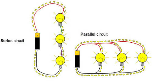
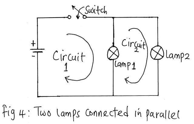
There is a way to connect the two lamps so that the full voltage of the source will fall across each. This arrangement is called parallel connection.
)
Two elements are said to be in parallel when they have two points common to them.
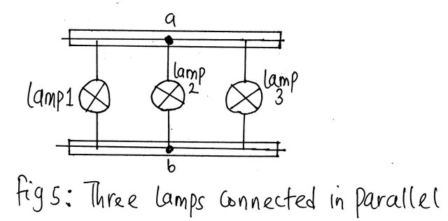
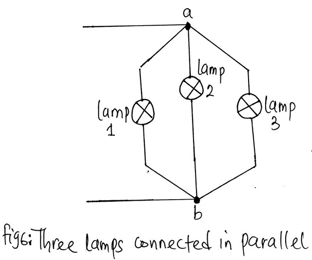
Consider figure 4,5 and 6 below. The connection in fig 4, 5 and 6 are termed parallel network. From fig 4, each of the parallel paths is called a branch. Therefore, in this case, there are two branches of the parallel network.
A close observation of fig 4 will reveal that there is more than one circuit in the arrangement and, whenever in any arrangement, there exists more than one circuit, we refer to it as a network. A network consists of two or more circuits.
Now that we are acquainted with series and parallel circuit, we can simplify it further by replacing the loads (lamps) with resistors. This move will help find out how to resolve resistances in series and parallel and how to get the equivalent resistance and its associated voltage and current distribution.
We will consider the series circuit first.
Resistors in Series
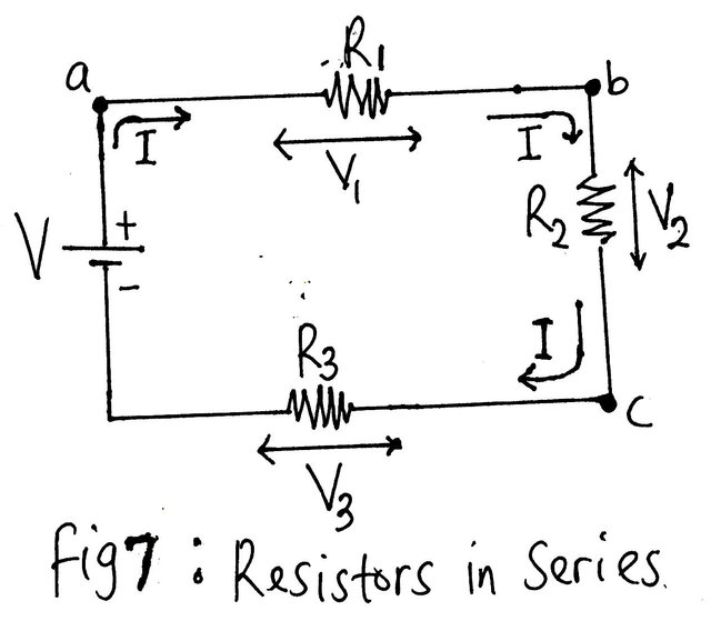)
Since in general, V=IR, we can say that the voltage across R1 is V1= IR1 (Ohm’s law). Recollect that in a series circuit, the same current passes through all the elements of the circuit. And thus, I is common to all the elements of the circuit.
V2= IR2
V3= IR3
V= V1+ V2+ V3…….(1)
Substitute the values of V, V1, V2, and V3 into equation (1)
IR=IR1+IR2+IR3
I(R)= I(R1+ R2+ R3)
R= R1+ R2+ R3……..(2)
)
No matter how many resistors are connected in series, the relation derived in equation (2) will hold and all you need to do is to amend the relation to suit the number of elements you have in series regarding the circuit being analysed.
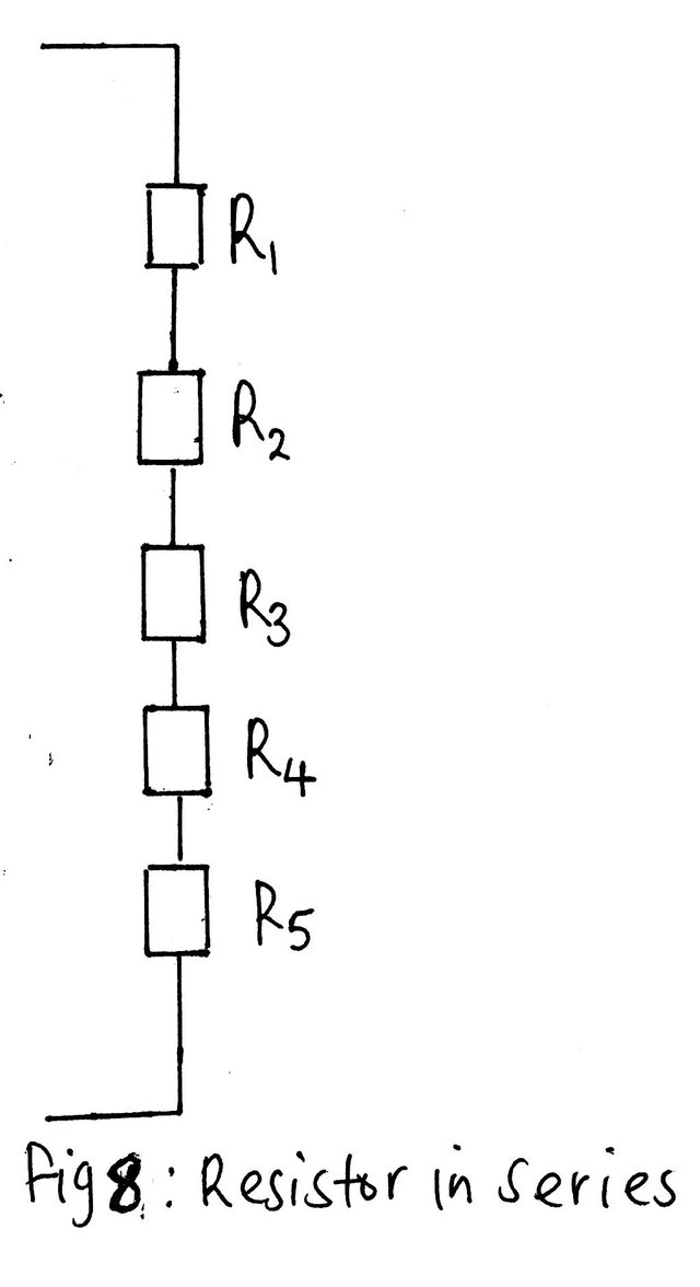
Consider the simple series circuit of fig 8, the equivalent resistance is:
R= R1+ R2+ R3+ R4+R5
Example
For the circuit of the figure 8 above, if R1=2Ω, R=3Ω, R3=4Ω R4=5Ω and R5=6Ω. Calculate the supply voltage V given that the total current is I and it is equal to 2A.
Solution
V1=IR1=2×2=4V
V2=IR2=2×3=6V
V3=IR3=2×4=8V
V4=IR4=2×5=10V
V5=IR5=2×6=12V
V= V1+ V2+ V3+ V4+ V5
=4+6+8+10+12=40V
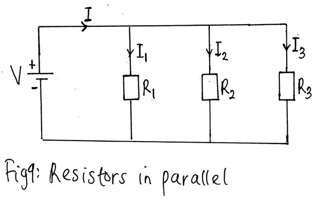
Parallel Resistors
Just like in series circuit, we will replace the lamp with a simple resistive load.
)
I= I1+ I2+ I3………(3)
As we have discussed, the voltage across elements in parallel are equal, but the current distribution s dependent is dependent on the magnitude of the resistor. Assuming you have two resistors in parallel with unequal values, the smaller of the two resistors will pass more current while if equal, they share the same current.
We will consider the current in each of the resistors in turn.
The total current I=V/R; I1=V/(R1) ; I2=V/(R2) ;I3=V/(R3).
The voltage across each element are the same. Substituting the value of I, I1, I2, I3 into equation (3) will yield:
V/R= (V )/(R1) +V/( R2)+V/(R3)
V(1/R) = V ((1 )/(R1) +1/( R2)+1/(R3))
(1/R) = 1/(R1) + 1/(R2) + 1/(R3)……….(4)
Where R is the total resistance
No matter the number of resistance connected in parallel, the relation of equation (4) will hold and all you need to do is adjust the relation to the number of parallel resistor in the circuit to be analysed.
References
Being A SteemStem Member
You have been consistently in sharing the fundamentals of electrical engineering and this has been particularly refreshing for me. I like the simplicity with which you presented the parallel relationship.
Many thanks, I am happy you were able to get some useful information from the post.
The knowledge of series and parallel arrangement of resistors is very essential in the analysis of more complex circuit. Of much importance is the knowledge of current distribution through the elements of the circuit. This knowledge is facilitated by a good grasp of series- parallel arrangement.
Many thanks for such a clear understanding of the post.