Alignment and Reorientation of Magnetic Domains and its Contribution to Energy Losses in Electric Machines and Transformers
The permeability of ferromagnetic materials is considerably high as compared to that of free space, which is calculated to be up to 6000 times that of free space. The permeability of free space is constant while that cannot be said of iron and other ferromagnetic materials.
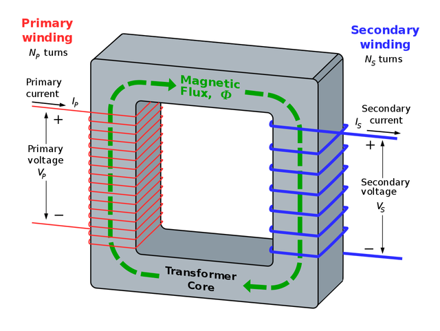
To analyse the behaviour of magnetic permeability in a ferromagnetic material, it is imperative we apply a direct current to an iron core and study the relationship between the magnetomotive force, permeability and the resulting flux.
Magnetomotive force is the counterpart of electromotive force in an electric circuit. Flux in the magnetic circuit is the counterpart of current in an electrical circuit, while permeability is the counterpart of conductivity in an electric circuit.
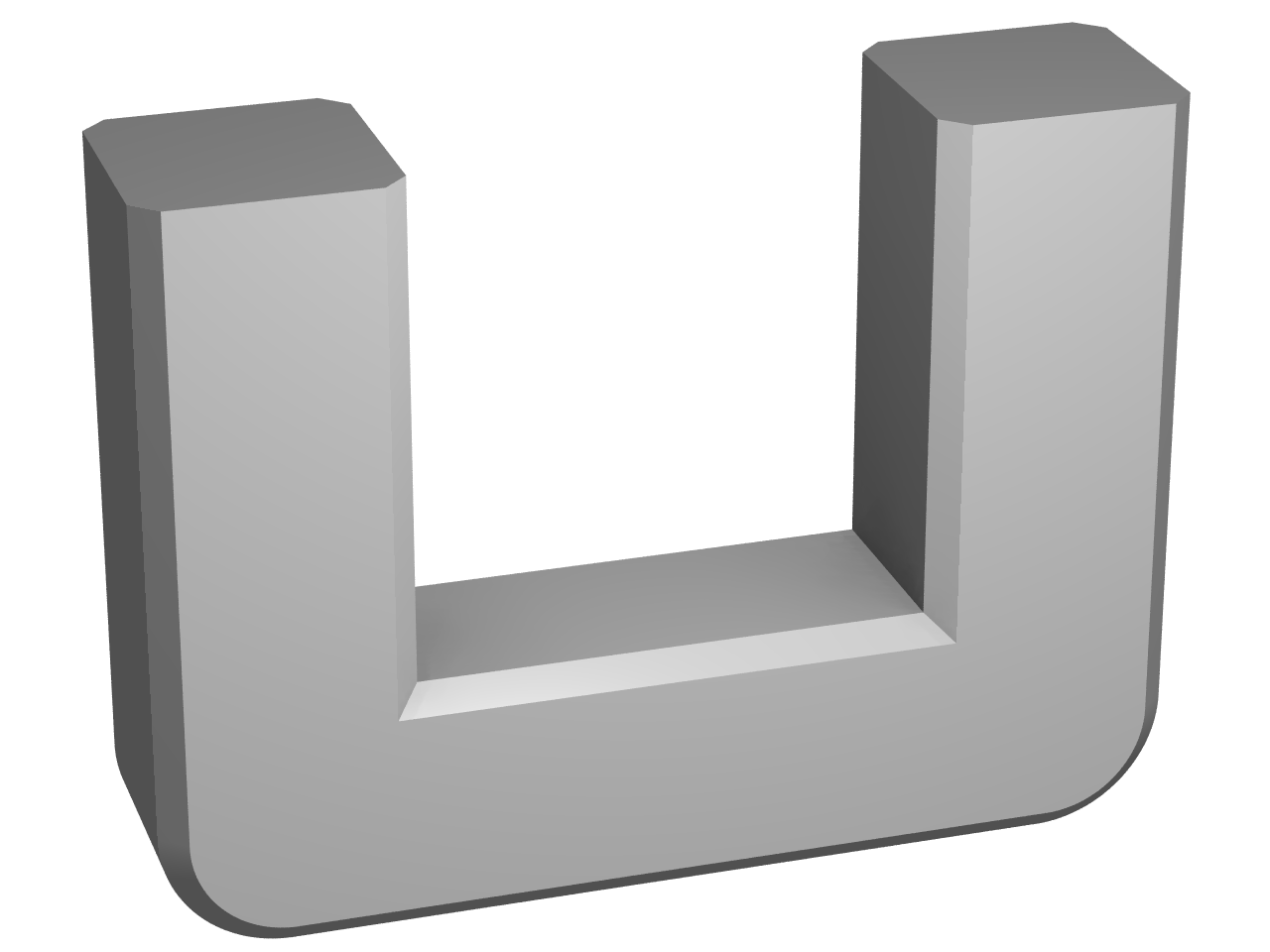
Consider the core of a magnetic material shown below:
When you subject the core shown above in fig 1 to a direct current and increase it slowly from zero amperes until the maximum permissible voltage is reached, the current will produce a flux and this flux is made possible by the pressure of the magnetomotive force in a similar fashion as would a voltage provide the driving force in electric circuit.
If the flux produced in the core is plotted against the magnetomotive force producing it, the plot that will result will take the form as shown below:
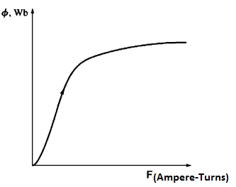
This plot is known as the saturation curve or a magnetization curve. At the onset, a small increase in the magnetomotive force generated a massive increase in the accompanying flux. This direct relation will continue until a certain point is reached where further increases in the magnetomotive force will not produce a commensurate increase in flux but will tend to produce relatively smaller flux. It will culminate at a point where an increase in the magnetomotive force results in no change in the flux at all.
This threshold is called the saturation point of the core. Notice from fig 2 that the saturation point is depicted by the region of the curve that is flat
On the other hand, the core is said to be unsaturated at the region where the flux varies very rapidly, and this region is the unsaturated region of the curve. The point that separates the saturated area and the unsaturation region is called the transition region is sometimes called the knee of the curve.
Note that there is a linear relation between flux produced in the core and magnetomotive force is linearly related to the applied magnetomotive force in the unsaturated region and tends to a constant value irrespective of magnetomotive force in the saturated region.
When you scrutinise the curve, you will notice that the permeability is massive and relatively constant in the unsaturated region and then gradually reduces to a very low value as the core becomes overly saturated.
The Ferromagnetic core is utilised in the construction of cores of electric machines and transformers because we can get a much more significant flux for a given magnetomotive force with iron as compared to what is obtainable with air. This advantage of higher flux with using iron core is sustainable as long as the core is operated in its unsaturated region which is situated below the knee of the curve of the magnetisation curve.
Almost all real electric machine such as generators and motor relies on magnetic flux to produce voltage and torque and as such must be operated near the knee of the curve where the core is unsaturated and can provide a flux proportional to the applied magnetomotive force.
This non-linearity can be used to explain hysteresis losses, coercive forces, remnant magnetism and the alignment of the magnetic domain.
Energy Losses in a Ferromagnetic Core
To examine the energy losses in a ferromagnetic core, we can decide to apply the alternating current in place of direct current and watch what the outcome.
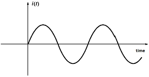
We will assume that the flux in the core is initially zero. With the initial increase in current, the flux in the core traces out path ab as shown in Fig 3 below. With the fall in the current as is customary with AC that has maximum value in the positive half cycle before it drops to zero before increasing to the maximum in the negative half cycle, the flux marks out a different part from the one it traced when the current increased in the positive half cycle.
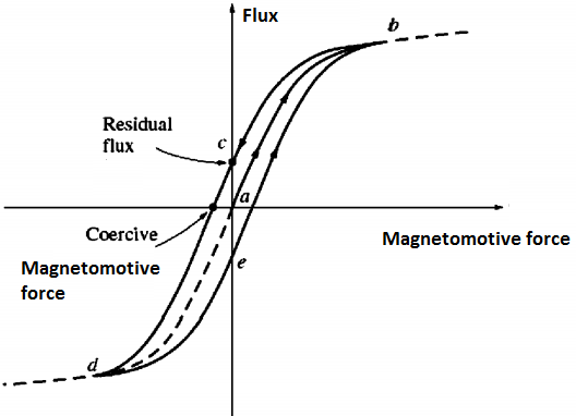
As the current decreases, the flux in the core follows path bcd, afterwards when the current increases again, the flux goes through path deb. It is important to note that the amount of flux that is in the core does not only depend on the amount of current applied to the windings of the core, but also the history of the flux in the core has to be taken into consideration.
When you look at the flux pattern, you will notice that it has the shape of a loop. This loop is a result of the previous history of flux in the material and the inability of the flux to maintain a specific path in its movement. This loop is known as the hysteresis loop.
From the diagram of the hysteresis loop, it is easy to see that if a huge magnetomotive force is applied to the core and consequently removed, the flux path that will be traced is abc, and with the removal, the flux will not go down to zero with the current. Instead, there is a magnetic field that will linger in the core. This magnetic field is known as remnant magnetic field or the residual magnetic field in the core.
It is precisely in this manner that permanent magnets are formed. For the flux to drop to zero, there will be a need to apply a force in the form of magnetomotive force applied in the direction opposite to the direction of the initial magnetomotive force. This magnetomotive force is known as the coercive magnetomotive force.
One may wonder the reason for the occurrence of hysteresis, but the reason is revealed with a little knowledge of the behaviour ferromagnetic materials and understanding of their structure.
A study of atoms of iron and like metals such as cobalt nickel, and their alloys shows that they have their magnetic fields closely aligned with each other. If we can look inside the metal, we will be able to see many small regions called domains.
Atoms in each domain are aligned with their magnetic field pointing in the same direction, and as a result, one can describe each domain within the material as a small permanent magnet.
These domains within the material are randomised and as a whole has no specific direction in which it is pointing, and for this reason, it would seem that a whole block of iron has no flux.
We can visualise the domain structure within a piece of iron by studying the diagram below:
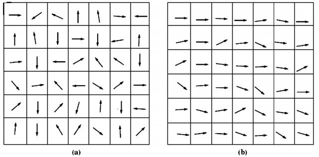
If we are to apply an external magnetic field to a block of iron, we will notice that domains that have direction similar to that of the external magnetic field will grow ahead of the other domains that were aligned maybe opposite to that of the external magnetic field.
This growth in the domains pointing in the same direction as that of the magnetic field is due to atoms in these domains physically alter their orientation to align themselves with the applied magnetic field. Whenever an extra atom is aligned to be in the direction of magnetic field, the magnetic flux in the atom is increased which causes more atom to switch orientation thereby increasing the strength of the magnetic field.
The superior permeability of iron as compared to air is as a result of this positive feedback effect due to the realignment of magnetic domains of the atom within the domain.
With the reorientation of the magnetic domains, the strength of the external magnetic field continues to build up, until the whole domains that are aligned in the wrong direction finally reorient themselves as a unit to line up with the external magnetic field.
In the end, when virtually all the atoms and domains in the iron are lined up with the external field, any further increase in the magnetomotive force will only result in the same flux increase as is obtainable in free space.
We can describe the period of reorientation and aligning of the magnetic field of the iron with the external magnetic field as the part below the knee of the curve in the plot of flux against magnetomotive force. Remember we described this region below the knee of the curve as the unsaturated region where the increase in flux is proportional to the increase in the magnetomotive force.
We can further consider the state of the iron when all the magnetic domains have been aligned to be the saturated region which is above the knee of the curve in the plot of flux against magnetomotive force.
The exciting part of hysteresis is that with the removal of the external magnetic field
the domains remain intact without undergoing randomisation.
What could be the reason behind this behaviour of the domains for lining up irrespective of the removal of the external magnetic field?
The reason is that we must expend energy in scattering the atoms. Initially, energy was expended by the external magnetic field to achieve the alignment; but with the removal of the energy, there is no source of energy to cause all the domains to rotate back. The piece of iron has been converted to a magnet by the process.
With the alignment of the domains, some of them will remain aligned until a source of external energy is supplied to change them. Some example of these sources of external energy that can alter the boundaries between domains or the alignment of domains is the magnetomotive force applied in the reverse direction, heating and a huge mechanical shock.
Any of these events can impart energy to the domains and enable them to change alignment. This reorientation of domains is the reason why a permanent magnet can lose its magnetism if it is dropped, hit with a hammer, or heated.
Conclusion
The energy needed to align and randomise the magnetic domains in the iron core results in a common type of energy loss in all machines and transformers. In each cycle of the alternating current, say positive half cycle, there is an alignment of the domain in a specific direction, but in the negative half cycle, there is a realignment in the opposite direction. Thus, the energy needed to achieve the reorientation of domains during each cycle of the alternating current applied to the core is known as hysteresis loss.
It can be proved that the area encapsulated by the hysteresis loop established by applying an alternating current to the core is directly related to the energy lost in a given AC cycle. The area of the hysteresis loop has a direct relationship with the level of magnetomotive force applied to the core.
There is no perfect machine that does not experience a certain type of loss. Hysteresis loss is unavoidable in electrical machines and transformers owing to the energy expended in alignment and reorientation of the magnetic domain. The study of magnetic behaviour of iron gives insight to the hysteresis loss and how a permanent or temporary magnet can be formed. Those materials Tha can easily be magnetised are called ferromagnetic materials. In-between ferromagnetic and diamagnetic material is paramagnetic material whose ability to be magnetized lies inbetween that of ferromagnetic and diamagnetic materials. Keep up the good work. The quality of your posts speaks for itself.
Thanks for your input, It is a pleasure to have people of your quality here. I appreciate the time you invested in reading through.
You are very much welcome.
@kaydee you wrote with the full authority in electrical engineering but I think you should keep it down a bit or pause once in a while to explain the point an average scientist might find difficult to understand. The whole point is to communicate but trust me few will understand the real message passed here.
Thanks for throwing more light on hysteresis loss. I didn't really understand how serious this is until the first two phase transformer i wond for my little project blew up in heat after making noise for several hours
Thanks for the observation. I assure you it is my target to make it as simple as possible for everyone. But you must appreciate that some backgrounds are better suited for some understanding of certain works. But I will definitely do another post to water it down. I love you all. I promise to carry you all along next time.
Congratulations @kaydee! You received a personal award!
Click here to view your Board
Do not miss the last post from @steemitboard:
Congratulations @kaydee! You received a personal award!
You can view your badges on your Steem Board and compare to others on the Steem Ranking
Vote for @Steemitboard as a witness to get one more award and increased upvotes!