Optical Fiber Technology: Taking a closer look
Fiber optics technology is the backbone of today’s internet. It has come to stay because it promises speed without measure with only glaring disadvantage being cost. Talk about internet speeds I’d say I’ve had my own share of slow internet speeds but the funny thing is that I didn’t know I was using the slowest internet access medium.
Back in 2008 I use to go for all night browsing with nothing but my 25MB memory card and adapter hidden in my pocket which I used to collect downloaded songs from the internet during my night browsing when the network admins must’ve slept off. They were using dial up modems which offered about 56 kilo-bit per second access speed with about 15 desktop computer accessing the internet via LAN cables. Little wonder why they made sure no one was downloading files when using their network.
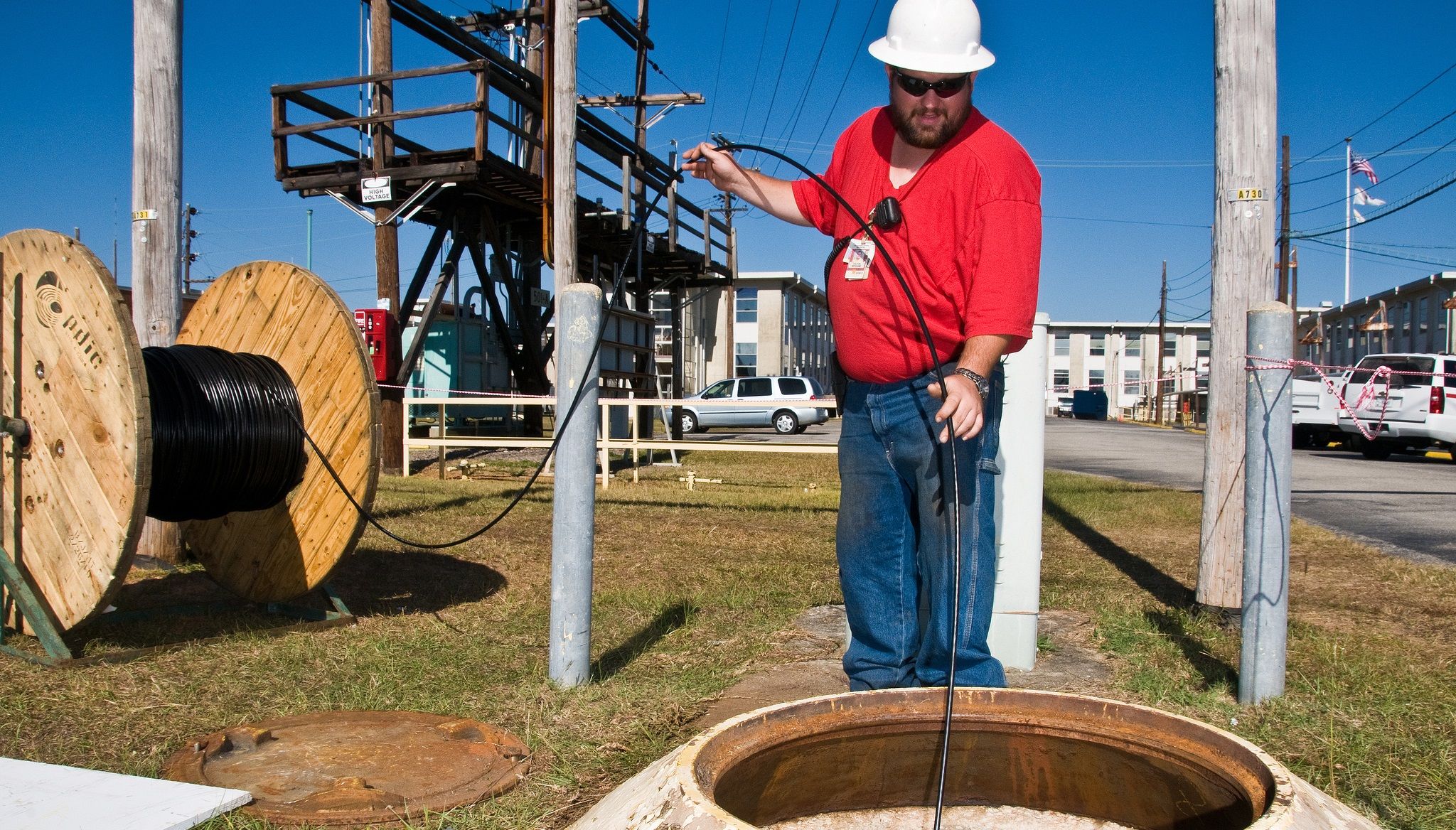
[credit: flickr. creative commons 2.0 license. author: unknown]
Fiber optic technology is no new technology as its origin dated back to 1880 though it was in research state for a very long time. The first city to receive fiber optics connectivity was Torino in Italy and this was back in 1977.
PRINCIPLE OF OPERATION

))
[ credit: wikimedia creative commons 2.0 license. Author: ictas]
Back in my high school days, we used to buy gifts for out-going students. One day I was out with my friends searching for a good flower bouquet in the market and while scouting the market, I saw a very brilliant light coming from strands of light colored plastics in an inverted broom-like structure with its base in a plastic siting and I can tell there was some electronic circuits in the enclosure.
Whenever I explain what is going on in those thick black fiber cables to newbies, this very electronic flower comes to mind because that exactly is the brain behind that tiny cable that puts into rest your worry about slow internet speeds.
With optics in the name, it’s no news saying that fiber optics technology has to do with transmission of data using light. Light waves if not obstructed or absorbed can travel to great lengths though some characteristics of wave travel like dispersion can greatly affect its propagation and this is why light source for the optical fiber medium is usually from a precise source like special LEDs and lasers.
The principle of total internal reflecting of light is leveraged in fiber optics.Internal reflection occurs when light falls on a medium with lesser refractive index (say from water to air) this makes the light ray to bend away from the vertical angle or the normal making the reflected angle to be greater than the incident angle.
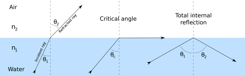
[credit: wikimedia. Creative Commons Attribution-Share Alike 3.0 Unported license. Author: Josell7 ]
At some critical angles, the reflected angle will tend towards the normal, this critical angle can be denoted by θc. Total internal reflection occurs when angle of incidence is higher than the critical angle. The critical angle can be obtained theoretically by setting the angle of refraction equals to 90 in the Snell’s law. Mathematically;
θc=sin^-1(n1/n2Sin90)
Where θc = critical angle
n1 and n2 are refractive indices of the two media.
Imagine a tube made of cylindrical mirror and can be bent without cracking. If light, may be from a torch is flashed into one end of the tube, it is very possible to completely recover the transmitted light from the other end of the tube. Fiber cables are made with flexible glass and in reality, it is not allowed to experience serious bend and in situations where these bends (angles less than about 130 degrees) are required, a device called enclosure is used to redirect the cable.
STRUCTURE
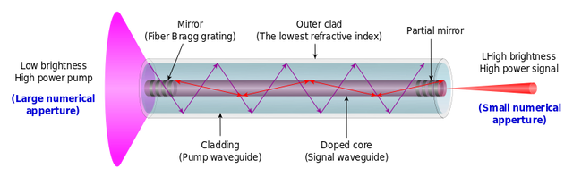
Unlike other signal transmission media like the twisted pair cables and coaxial cables where the basic structure/configurations are the same, fiber cables are very complex and have varying configurations and structures and require professional attention during installation and maintenance. The structure of the cable determines its speed and the distance it can safely propagate information within it. There are basically three parts of the fiber cable, these are:
[credit: wikimedia. CC0 1.0 licence. Author: Author: Danielsoh8]
The core is made up dielectric material (electrically non-conducting materials at room temperature like glass or plastic). This is where the total internal reflection of light wave described above takes place. The core helps to guide the light wave throughout the cable length. The size of the core determines how fast and how long information can travel within the cable. The size of the core creates two different type of fiber cable;
Single mode fiber cable has core that are very small in diameter. With its little diameter, just a single mode of light (single light ray) is allowed to propagate through the system though transmission can be done in different frequencies. This ensures a limited number of reflections in the core thereby reducing interference. This means that reduction in signal strength called attenuation, as the light travels through cable is greatly reduced.
This also means a gain in overall bandwidth and longer distance transmission. Charles Kuen, a Chinese electrical engineer was awarded a Nobel Prize in 2009 for his awesome contribution in the single mode optical fiber system. Single mode optical fibers can transmit information at speeds up to 10 GB/s for a distance of 80 kilometers!
Multi-mode fiber optics has core with larger diameter which allows many modes of light to propagate thereby increasing the number of reflection within the tube.
))
[from top; graded index, multimode and single mode credit: wikimedia Creative Commons Attribution-ShareAlike 3.0 licence. Author: unknown]
They are prone to attenuation due to signal distortion as are result of difference in propagation speeds of light signals at different modes. This is referred to as modal dispersion. Because of this, signals can safely travel for a maximum distance of 2 kilometers with data speeds of 100 megabits per second, 1 kilometer with data speeds of 1 gigabit per second and up to 580 meters with data speeds of up to 10 gigabits per second.
Prior to the year 1953, cladding was not part of the fiber optics technology this means that light rays were lost in the course of propagation. In 1953, Heel Bran, a Dutch scientist discovered a way of combating this loss in light rays by coating the core with an ultra-pure glass called cladding. The cladding is made with material of lesser refractive index than the core and not only helps in guiding light rays through the optical ducts but also reduces light scattering at the surface of the core and also functions as a protective against contaminants to the core.
Some fiber cables houses very advanced cladding in which light not only travels through the core but also through the cladding allowing for more bandwidth and longer distance. Earlier cladding contains modes which are as a result of the fact that apart from the core, the cladding is the next material with higher refractive index allowing lights to be trapped in the cladding and this is highly undesired as these trapped lights creates signal distortion. Modern optical fiber cables comes with another coating over the cladding which has higher refractive index than the cladding and this results in attenuation of unwanted light rays in the cladding.
Though the cladding provides mechanical protection of the core to a great extent, the buffer provides even more mechanical protection for both the core and the cladding. The buffer is made of very elastic plastic and helps prevent abrasions on the cable. Bending of the fiber cable is highly prohibited since it can damage the bent portion, hence the buffer is stiff and hard to bend which helps prevent microbends when the cable is being passed many kilometers into its ducts.
SPLICING AND TERMINATING THE FIBER OPTIC CABLE
I guess we all know the popular coaxial cable which contains just two cables; the straight copper core and meshed silver coating. Joining this cable is very simple and straight forward, the same goes with terminating the cable. The same goes with the legendary shielded and unshielded twisted pair cables. Twisted pairs are terminated with registered jack 45 connectors and can be connected easily to our computer using the Ethernet ports or to the Macintosh computers using a special adapter.
The same cannot be said for the optical fiber cable. The process of joining two or more fiber cables is called splicing. Other method of joining fiber cables is the connectorization method, though this method is not popular because of loss in signal strength due to back reflection of light. There are two method of fiber splicing, these are;
In mechanical splicing method, the two cables to be joined are held together by a mechanical device which aligns the two ends of the cables in a very precise manner allowing light to pass from one fiber to the other. The loss in signal strength measured in decibel is up to 0.3.
))
[A fusion splicing machine credit: flickr creative commons 2.0 license. Author: Dennis van]
In fusion splicing, the ends of the two cables to be joined are precisely aligned and their glasses welded together using either heat or electric arc giving rise to almost a perfect junction with signal loss being less than 0.1 decibel.
The steps involved in splicing fiber cables are very complex but if there’s need to explain the procedures, I’ll do that in the comment section.
TERMINATING FIBER CABLES
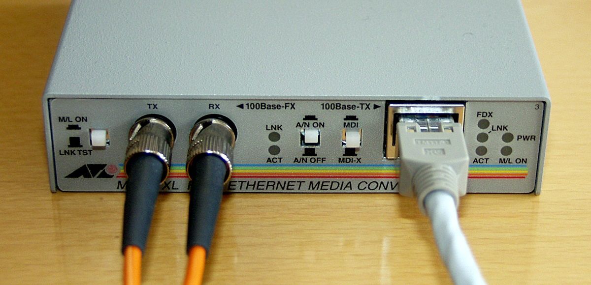
[A media converter showing ST connectors, Transmit(tx) and receive (rx) terminals (left) and registered jack 45 (RJ45) connector and unshielded twisted pair cable (right). Original image available at wikimedia. Creative Commons Attribution-Share Alike 3.0 Unported license. Author: Little Joe]
The ends of fiber cables are not just plugged into our computer directly. Our computer by default understands electrical impulses and hence cannot directly process information transmitted optically. A device called Media Converter is used to convert the light signals into electrical signals and can give us output through a twisted pair which can be connected directly to our computer. Some network equipment can directly access information from the fiber cable using a special port called SFP (small form-factor pluggable) port allowing more than two fiber cables to be bundle together to produce even high speeds.
REFERENCES
- communication media -whatwhenhow
- Basic structure of optical fiber -tbup
- optical fiber connectors -wikipedia
- splicing guide -tecratools
- single mode vs multimode fiber optic cable -multicominc
- Cladding -wikipedia
- Modal dispersion -wikimedia
- Single mode optical fiber -wikipedia
If you write STEM (Science, Technology, Engineering, and Mathematics) related posts, consider joining #steemSTEM on steemit chat or discord here. If you are from Nigeria, you may want to include the #stemng tag in your post. You can visit this blog by @stemng for more details. You can also check this blog post by @steemstem here and this guidelines here for help on how to be a member of @steemstem.

Hahahahahaha.......
This post must have emanated from the fibre implementation you are currently carrying out in Federal University of Technology, Owerri.
Well done bro.
Boss you caught me unawares, lol. Yeah, I felt like taking a piece out of my job. Thanks boss.
Hey, please note that saying 'cc0' can be confusing for curation if the pictures are in fact cc2.0 or otherwise, as the above images actually are!
some are even cc3.0 but I thought it would create confusion. But the correction have been made, thanks.
The fire optics cable i remember using them in cafes for internet or local connection back then.
They were amazing. Thanks for the education on them.
it's quite fast and noise tolerant, the only issue i have with it is that it's very costly and requires expert handling, unlike other waveguides
This reminded me of when I used to go with my friends to set up LAN. We would spend major part of the time crimping RJ45 to Cat5e UTP. Lol.
Nice piece man
Hahaha crimping cables is usually a part of my daily routine, even if I don't have need cause it comes in handy during some very ugly troubleshooting. Thanks for stopping by bro.
Before i knew about fibre optics, i used to wonder what the cables buried underground were meant for.
Awesome post sir!