MY PERSONAL HAND-BUILT MICROPHONE SYSTEM
I come to you today with my own form of a steemstem post. It turns out that my trying to follow steemstem post format (referencing and citing sources, of which I do), is not working out.
Will keep trying though because that is the steemit spirit.
I was teaching a friend @frank-cris electronics (I usually take students on electronics part-time).
Today we built a CONDENSER MIC SYSTEM USING LM386.
This post will be a walkthrough guide of how to build yours with full component list and step-by-step procedure.
STEP ONE: GATHER YOUR COMPONENTS
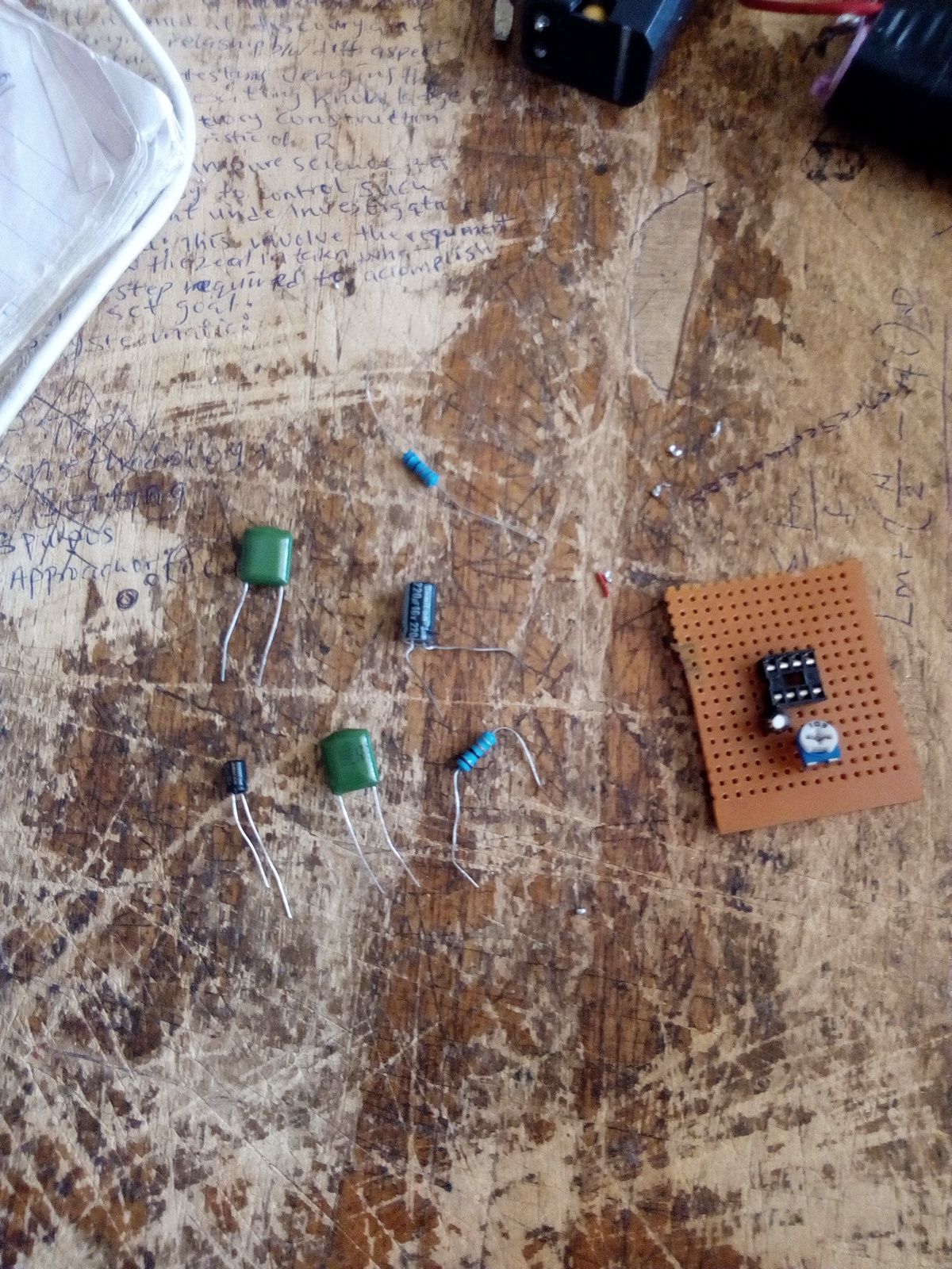
Image by me[@chiboyzz]
- Veroboard.
- 4*4 IC Socket
- IC LM386
- 10uf * 2
- 0.1uf (code=104) * 2. The second ceramic capacitor is actually 0.05uf but i used 0.1uf and it worked fine.
- 220uf 16v
- 10k * 2
- 10k V.R
- Speaker
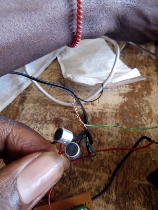
- Condenser Mic (you can get this from any old earpiece that has the receive call function)
Apart from the condenser mic, all other components were purchased at my local electronics shop.
Sorry i didn't highlight each component in the circuit, i started taking pictures after placing the IC socket and the capacitor you see in the picture
This is the circuit diagram below.
Image by Circuit Digest
In the circuit, the second ceramic capacitor is actually 0.05uf which is not available in the electronics market where i shop for electronics, so i improvised and went for 0.1uf.
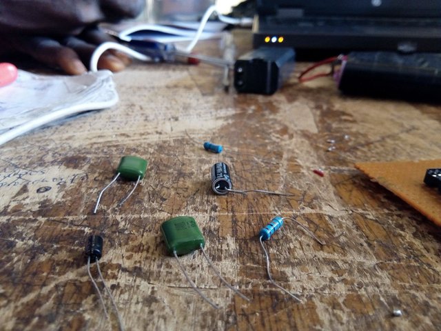
Image by me[@chiboyzz]
STEP TWO: GET YOUR VEROBOARD AND PLAN ENOUGH SPACE FOR YOUR CIRCUIT
This step is paramount depending on the complexity and function of the circuit you are to build.
FUNCTION
This is your purpose of building your circuit in the first place. Say i am to build and inverter circuit.
First i will make sure that my veroboard can contain all the components and also plan how i will route my solder connections beneath the veroboard to suit the casing of the inverter.
COMPLEXITY
The space you plan for your circuit on your proposed veroboard can be affected if the circuit is very complex in nature. This means that there will be more components, meaning more space to be occupied on the veroboard.
STEP THREE: START PLACING YOUR COMPONENT AND SOLDER JOINTS TO THEM.
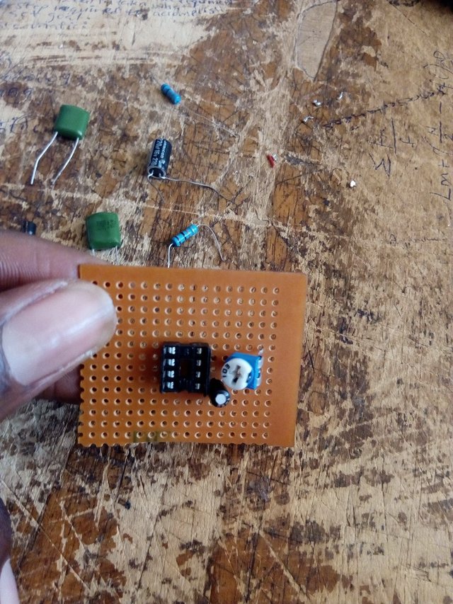
Image by me[@chiboyzz]
This is the most important part of building any circuit. The position of each components determine how the solder joints below the veroboard will be.
If look closely, you will notice that i did my solder joints and jumping neatly to avoid clustering of components and confusion when troubleshooting the circuit(in case of any fault after testing)
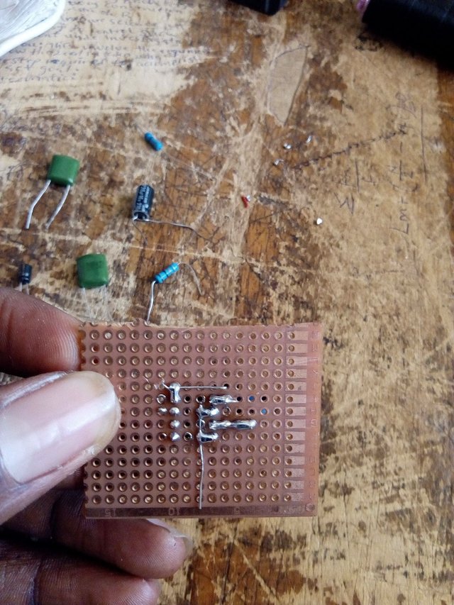
Image by me[@chiboyzz]
STEP 4: FOLLOW THE CIRCUIT PROPERLY.
This is the follow-up of the previous step. There really isn't much to building a circuit. In my next project build, i will cover the construction process with video as well so as to elaborate more on solder joints and space planning during circuit building.
.jpg)
Image by me[@chiboyzz]
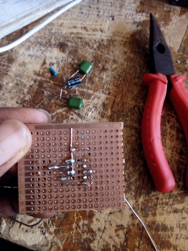
Image by me[@chiboyzz]
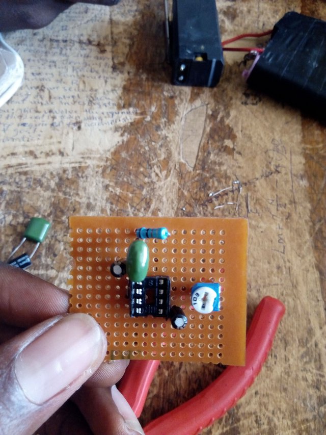
Image by me[@chiboyzz]
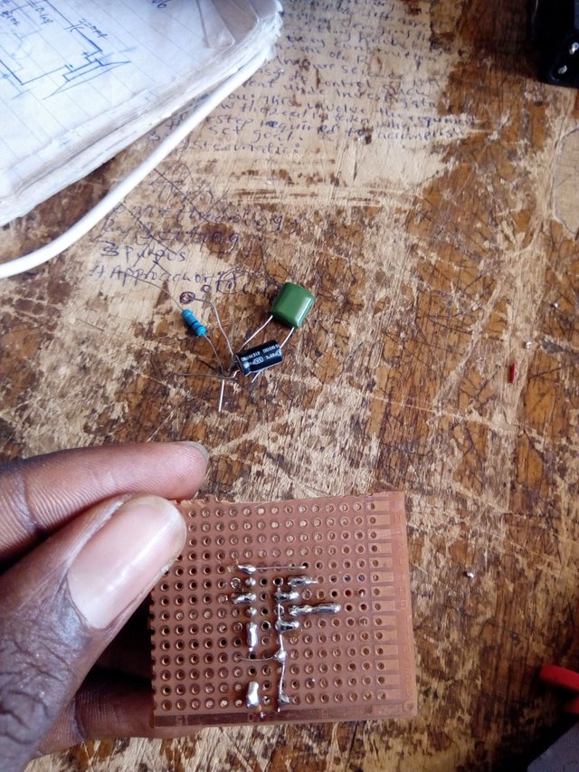
Image by me[@chiboyzz]
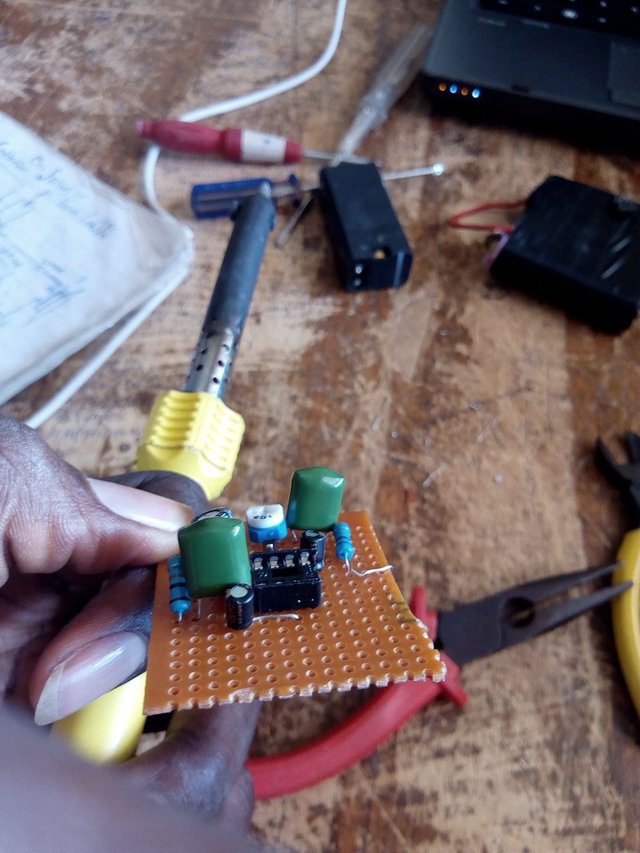
Image by me[@chiboyzz]
FINAL STEP: THE FINAL LOOK OF THE CIRCUIT
This is what the circuit looked like after building. Notice the solder joints and the condenser mic.
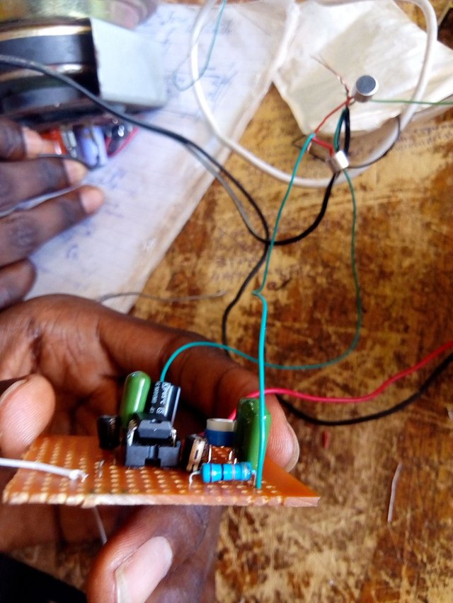
Image by me[@chiboyzz]
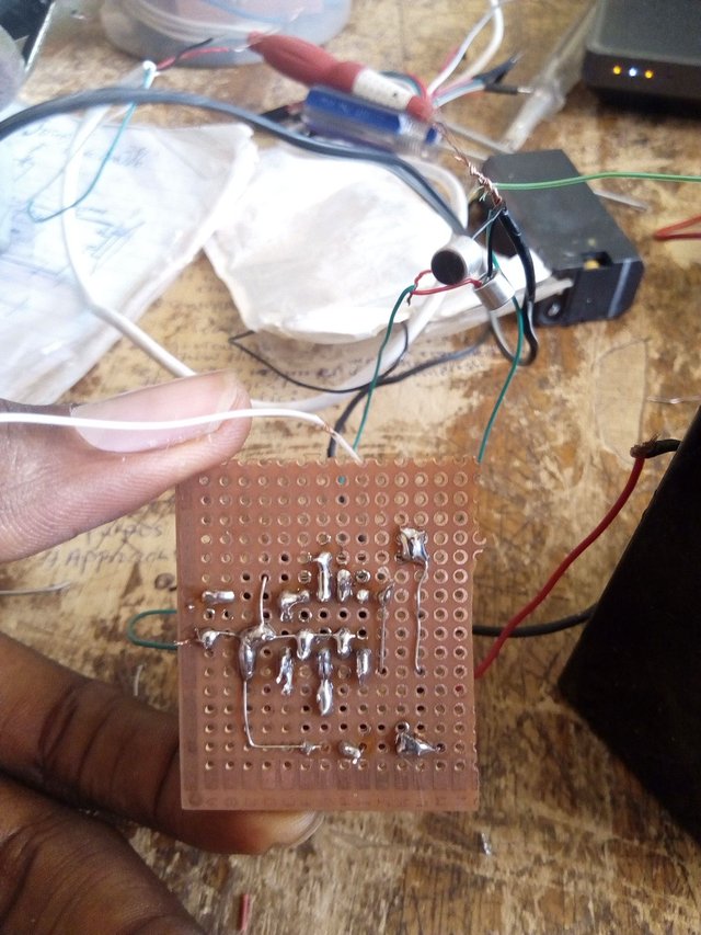
Image by me[@chiboyzz]
The condenser mic in the picture below is gotten from an old earpiece.
References
If you write STEM (Science, Technology, Engineering, and Mathematics) related posts, consider joining #steemSTEM on discord here. If you are from Nigeria, you may want to include the #stemng tag in your post. You can visit this blog by @stemng for more details. You can also check this blog post by @steemstem here and this guidelines here for help on how to be a member of @steemstem. Please also check this blog post from @steemstem on proper use of images devoid of copyright issues here
.gif)
I really like your article!
I think it is a simple yet good proof that you can make something out of passion, without having to rely on expensive parts. Now, what accurate is it? Could you test it?
I just made a video of it being tested. Will post it today