Laser Locking For Ultra-High Precision Light.... Pound-Drever-Hall Laser Locking Method..... In Depth!
Laser Locking For Ultra-High Precision Light.... Pound-Drever-Hall Laser Locking Method....
Used For High Precision Laser Light To Ensure Accurate Measurements, PDH Technique Is Fundamental!
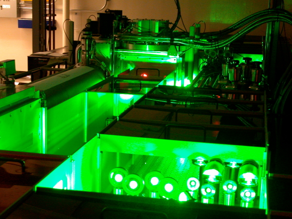
Image Credit:- newscenter.lbl.gov

Introduction
This artcile focuses specifally on a technique used with lasers called locking, it allows scientist to use very fine tuned light.
I'm sure everyone is familiar with a laser, and have probably used one. You will notice that lasers have a single colour, this is because it is a single frequency with a very small range. They are extremely useful in many measuring devices from spectrometers to gravitational wave detectors. Its is they were fine range of frequencies that make them ideal. However in many cases for high precision the laser light must be as close to a single frequency as possible. In order to do this a filtering cavity is first used that only allows a very small frequency band of light through.
The cavity only allows light to enter a very small band also, so to ensure that the light is always at the right frequency to enter and thus leave a locking method must be used. Once this is acheived, the light that leaves the cavity can be used for other purposes like making very precise spectroscopic measurements of atoms or molecules. The gravitational wave detector also works with the same principle described in this article.
The Pound-Drever-Hall locking method is at the heart of Laser experiments.

Overview
The transmissive and reflective behaviour of the cavity strongly depends on the frequency of the laser  with respect to the cavity length
  . Maximum transmission occurs when the frequency of the laser on resonance with the cavity mode. The cavity is subject to fluctuations, such as temperature changes and external mechanical vibration, which leads to small perturbations in the cavity length. In order to maintain maximum transmission the laser frequency must be continually adjusted to match the resonance mode of the cavity.
Locking a laser refers to the action of ensuring the laser always matches a resonant mode of the cavity. The Pound-Drever-Hall (P.D.H) method is the favoured technique of locking; established in 1983. Ron Drever envisaged this method that was based on techniques for microwaves used by R.V.Pound. The technique was further developed and implemented by Jan Hall. It's possible with the P.D.H locking method to adjust either the laser frequency or the cavity length by using a piezo actuator. In either case the the resonant mode is locked onto , and maximum transmission occurs. Using this method and carefully isolating any fluctuations it's possible to achieve sub-hertz stability.
The Method
A laser operates with an unstable frequency within a certain bandwidth, the frequency must be actively controlled in order to match the cavity mode. It's imperative to continually measure the difference between the laser frequency and the cavities resonant mode, this difference is  . This measurement is fed back into the laser to adjust it's frequency and obtain resonance once more.
To date there are no electronics available to directly measure the difference in frequency  , instead it can be inferred from the reflected light. When the frequency of the laser is far from resonance all of the light is reflected, near to the resonance less light is reflected, and at resonance no light is reflected so the reflection co-efficient goes to zero,
  . The reflection co-efficient
  depends on the frequency shift magnitude , in such a way that its symmetric around resonance. The problem caused by this symmetry is that it's not possible to determine which side of the resonance the laser is on. This means that adjusting the frequency in the wrong way could result in moving further away from resonance. The Pound-Drever-Hall technique is the solution to this problem.
The derivative of the reflection co-efficient with respect to the frequency shift is antisymmetric around resonance. This results in an error signal, which tells us which side of the resonance peak the laser is on. If the frequency is varied with a small change, the derivative can be obtained and therefore the response of the reflected intensity. Below resonance the derivative is negative, but is positive above resonance (see Figure 1). This allows us to adjust the frequency in the correct way to arrive back at resonance.
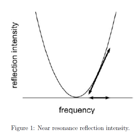
Image Credit:- Ref[1]
Implementation
A laser beam is sent through an electro-optic modulator (EOM) controlled by an oscillator, which modulates the phase and introduces side-bands to the carrier frequency of the laser. The light impinges on the input mirror of the cavity, and the reflected beam is recorded by a photo-detector. The signal from the photo-detector and the oscillator output is then mixed and passed through a servo amplifier (which is a PID controller), which acts to adjust the laser frequency and lock the laser to the cavities resonant mode.
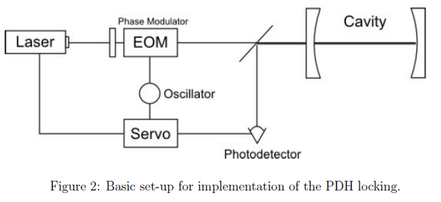
Image Credit:- Ref[1]
Extraction of the Error Signal
The extraction of the error signal is not immediately self evident, but through a mathematical representation it's easier to understand. For the purpose of an introduction, we can consider a Fabry-Perot cavity (seen in Figure 2) to build the formalism.
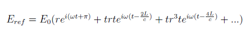
The magnitude of an incident electric field at the cavity is
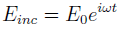
where a constant frequency  is assumed. The light reflected from the cavity has two components, the directly reflected beam, and some part of the cavities standing wave that leaks out through the mirror. The directly reflected beam experiences a phase shift of
  , however the leaked beam contains many phase components. After the first round trip of the cavity, there is a phase shift of
  after traversing the length of the cavity twice.
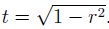
  is the angular frequency of the laser,is the cavity length and c is the speed of light. Providing the mirrors are the exactly the same, such that the reflection [r] and transmission [t] co-efficients don't differ between the mirrors, then the reflected beam will be
where
 . The reflection co-efficient is
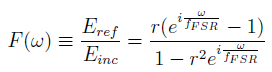
where 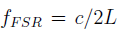 is the free spectral range of the cavity. The FSR is the separation in frequency between resonant peaks of the same mode. It can be seen from Figure 3 that the phase of the reflection co-efficient is antisymmetric around the cavity resonance frequency, so it's possible to use a function proportional to this as an error signal.
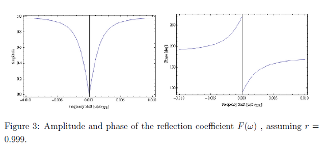
Image Credit:- Ref[1]
If we pass the laser through an EOM we induce some phase modulation, if the EOM modulates the phase with a frequency of  , then the electric field becomes
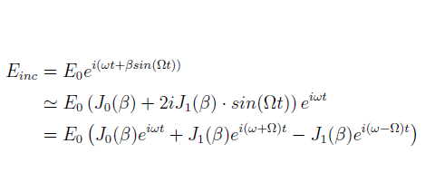
which is valid for small modulation depths  , and
, and  are the Bessel functions. Notice there are three components, the carrier band of the laser corresponds to
  , whilst the two
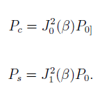
  components are the side bands produced by phase modulation from the EOM. The power of the carrier
 , and the side-bands
  is related to the total power P0 in the following way
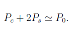
When the modulation depth is small  , nearly all of the power is contained in the carrier and two side-bands, such that
The phase modulated laser impinges on the cavity's mirror and some reflection occurs, each component of the frequency will be transformed through reflection, and the electric field becomes

There is still the problem of directly measuring the electric field, however using a photodiode detector we can measure the intensity or power that relates to the electric field as  . With some algebraic manipulation the reflected power can be expressed as
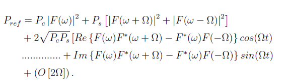
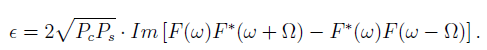
The reflected power contains frequency components of the oscillation from modulating the frequency that produces side-bands, the DC power of the carrier, and higher order components from the interaction of side-bands. In order to obtain the phase, oscillating terms must be separated. For fast modulation frequencies the sine term will dominate over the cosine term. It is proportional to the modulation by the EOM, and a mixer can be used to extract it. The mixer multiplies the sine term from the photo-detector with the sinusoidal signal produced by the oscillator, this produces a  term and a DC component. We can isolate the DC component using a low pass band filter, that provides the PDH error signal we desire, that is expressed as
From Figure 4 it can be seen that the error signal is antisymmetric around resonance, there is a large frequency range where the error sign(+ or -) relates to which side of the resonance the laser is on. Also a steep slope near resonance is beneficial for the server loop to produce the locking between the laser and the cavity.
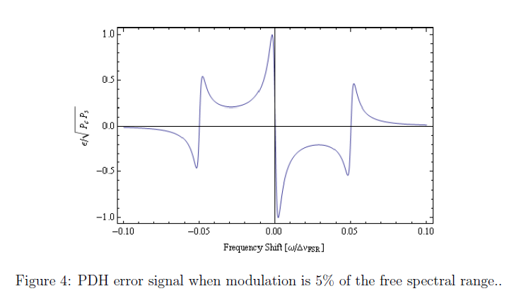
Image Credit:- Ref[1]
Personal PDH Signal
Using the technique described in this article i was able to generate this signal, use it to lock my cavity and detect the light allowed to transmit through the cavity via resonance. In the figure below you will see the PDH signal in blue and the resoance peak of the cavity mode in Red (don't worry about the x-axis in time). I can now use this light to make very small oscillator vibrate and study the motion or even cool them, but thats for another time.
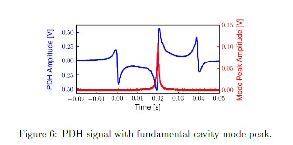
Image Credit:- Self-Produced in Python
I hope you enjoyed the article and found it interesting. Feel free to UPVOTE, FOLLOW and RESTEEM.
*No copyright infringement has occurred. The article was written by me. Pictures are either personal or free to use in the public domain. Figures in this article were extracted from Ref.[1]
References:-
[1] Eric Black:- Notes on the Pound-Drever-Hall technique, 1998

Thanks for writing in simple enough language so a layman can understand, and the images helped a great deal. I didn't get the part about symmetry and the use of derivatives to determine optimal direction, until I see what looks like a regular quadratic curve and suddenly the whole thing falls into place.
Hello there. Thanks for taking the time to read the article. I'm glad you found it understandable. It's such a important process and technique used with lasers. Without this method our measurements we make wouldn't be so precise, for example the line width associated to spectroscopic measurements would be large providing poor resolution.
Plenty more to come :)
I agree. It is amazing to see how new technology allows us to get really close to "exact" experimental procedures. My physics professor in university tells us that we can never make exact measurements; there is always some margin of error, be it human/experimental or random/circumstancial. It is important to do everything possible to make sure our measurements are as accurate as possible, although it can never reach exactitud.
Like we can make the value of 1/x go extremely tiny but it will never reach 0. Amazing.
Exactly! Spot on! When making using light there is a limit called the "shot noise limit". It's basically the limit we can reach of reducing the noise in the measurements. The light when detected when making measurement arrives at the detector in a "pitter patter" rather than a smooth continuous sinusoidal fashion. There are techniques to reduced this noise, we must "squeeze" the light, this puts more uncertainty in the amplitude but increases precision for the phase, or vice verse. However the Heisenberg uncertainty principle will always be there making everything in life uncertain hahaha.