Thermodynamic Cycles. Part 2
Brayton Cycle
Brayton Cycle (External Heat Transfer) The Brayton cycle, also called the Joule cycle, was originally developed using a piston machine with fuel injection, but now it is common to realize it in turbines with open or closed cycles. The cycle machine open can be used both with internal combustion and with transfer of external heat, while the machine with closed-cycle as a source of energy external The thermodynamic model of gas turbines is based on the Brayton cycle, although it is generalized as a thermodynamic cycle, in reality, the working fluid does not complete a complete cycle in the gas turbines since it ends in a different state When you started the processes, you could say that it is an open cycle. Simple open cycle gas turbines use an internal combustion chamber to supply heat to the working fluid and simply closed cycle gas turbines utilize a transfer process to add or remove heat from the working fluid.
Description of the cycle
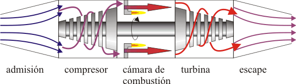
Admission
The cold air and atmospheric pressure enters through the mouth of the turbine.
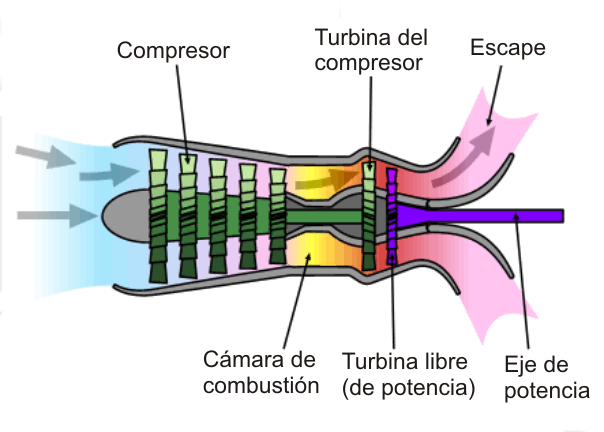
Compressor
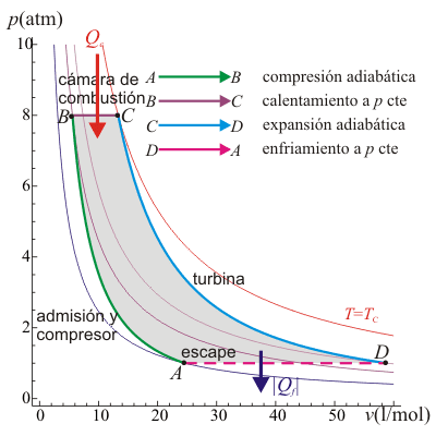
The air is compressed and directed towards the combustion chamber by means of a compressor (moved by the turbine). Since this phase is very fast, it is modeled by an adiabatic compression A → B.
Combustion chamber
In the chamber, the air is heated by the combustion of kerosene. Since the chamber is open, the air can expand, so the heating is modeled as an isobaric B → C process.
Turbine
The hot air passes through the turbine, which moves. In this step the air expands and cools quickly, which is described by an adiabatic expansion C → D.
Escape
Finally, the cooled air (but at a higher temperature than the initial one) comes out. Technically, this is an open cycle since the escaping air is not the same one that enters through the mouth of the turbine, but since it does enter the same amount and at the same pressure, the approximation of supposing a recirculation is made. In this model, the exit air simply gives heat to the environment and re-enters through the cold mouth. In the pressure and volume diagram, this corresponds to a constant pressure cooling
In the consequent, both a thermoelectric power station and a jet turbine of an airplane, operate with different ways of air compression. there are centrifugal compressors, in which the compressor drives the air to a chamber that runs around the periphery of that compressor. There are also, in the gas turbines, so that some corrugated fillets cause the pressurized gas to cause a rotary motion, and thus the movement of an axis. In jet planes, the commutator moves in solidarity with the work carried out by the pressurized gas of combustion in the chamber that exits through a back area of the turbine called a nozzle.
Rankine Cycle
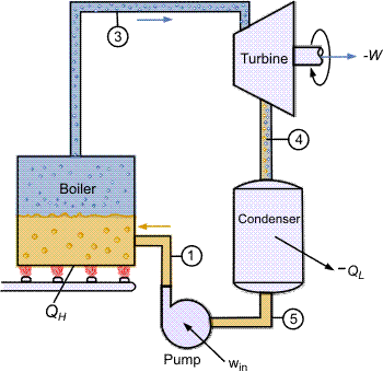
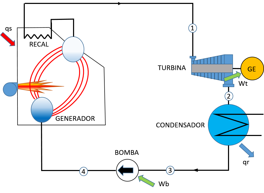
The simple Rankine cycle is the cycle commonly used by all plants power generators with steam. This cycle is conceived as a resource for use the characteristics of water as a working fluid and manage the phase change between liquid and vapor. Naturally, it is possible to use many other substances as working fluids, instead of water; the choice depends on several factors, including the need to adjust the heat transfer temperatures to the vapor and liquid states, while keeping the vapor pressures in the system low. It consists of heating water in a boiler until evaporating it and raising the vapor pressure. This will be taken to a turbine where it produces kinetic energy at the cost of losing pressure. Its path continues to continue towards a condenser where what remains of steam goes to the liquid state to be able to enter a pump that will raise the pressure to be able to enter it again into the boiler.
Description of the cycle
Process 1-2
Isentropic expansion of the working fluid in the turbine from the pressure of the boiler to the pressure of the condenser. It is carried out in a steam turbine or a reciprocating steam machine in which power is generated in the axis of the same.
Process 2-3
Transmission of heat at constant pressure from the working fluid to the cooling circuit, so that the working fluid reaches the state of saturated liquid. It is carried out in a condenser (heat exchanger), ideally without loss of load, the rejected heat can be used in most processes for other technological uses in the specific case of industries.
Process 3-4
Isoentropic compression of the working fluid in the liquid phase by means of a pump, which implies a power consumption. The pressure of the working fluid is increased up to the boiler pressure value.
Process 4-1
Transmission of heat to the working fluid at a constant pressure in the boiler. In a first stage of the process, the working fluid is heated up to the saturation temperature, then the liquid-vapor phase change takes place and finally saturated steam is obtained. This steam can be overheated in most cases by taking advantage of the energy of the effluent gases from the furnace in equipment called superheater, this high pressure steam is used by the turbine to generate the power of the cycle (the net power of the cycle is it gets really discounting the one consumed by the pump, but this is usually very small in comparison and is often neglected).
Otto Cycle
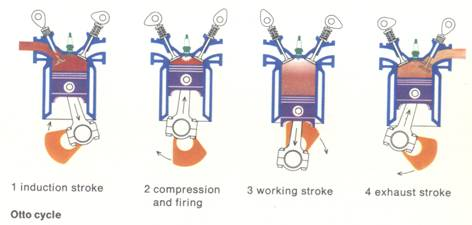
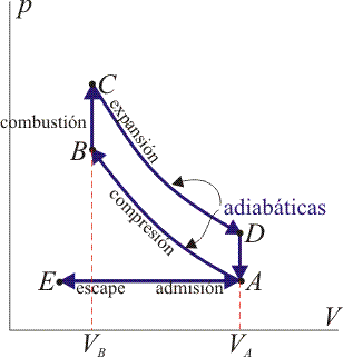
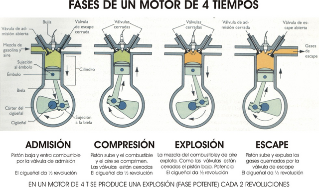
An ideal Otto cycle models the behavior of an explosion engine. This cycle consists of four steps and is a theoretical approach to the behavior of a spark plug ignition or explosion engine. Many of the thermal machines that are currently built (truck engines, cars, machinery, etc.) are equipped with a motor called a four-stroke engine. The cycle that describes the working fluid of these machines is called the Otto cycle, invented at the end of the 19th century by the German engineer of the same name. The gasoline engine is an alternative, internal combustion, spark ignition, four-stroke engine that converts the chemical energy contained in the fuel into kinetic energy.
The process begins with the homogeneous mixture of gasoline and air outside the combustion chamber in an element called a carburetor. The obtained mixture is sent to said chamber, where it is compressed. The combustion is initiated by an ignition system external to the timing motor (spark plug). Inside the cylinder ignites and burns the mixture of air and gasoline. The heat generated by the combustion causes an increase in the pressure of the gases, previously compressed causing a mechanical work through the piston, the connecting rod and the crankshaft. The burnt gases are expelled through the exhaust pipe and are replaced by a new mixing portion after each combustion stroke, all of which is produced according to the four-stroke principle.
Description of the cycle
Admission (1)
The piston descends with the intake valve open, increasing the amount of mixture (air and fuel) in the chamber. (Expansion at constant pressure because the pressure is equal to the outside when the valve is open). E-A
Compression (2)
The piston rises compressing the mixture, both valves remain closed (Adiabatic understanding). A-B. Combustion, With the piston in the top dead center, the spark of the spark plug jumps, which initiates the combustion of the mixture at practically constant volume (since the piston has not had time to lower). B-C
Expansion (3)
Due to the combustion, there is a sudden rise in temperature that pushes the piston down, doing work on it, the valves are still closed. (Adiabatic expansion). CD.
Escape (4)
The exhaust valve opens and the gas exits to the outside, pushed by the piston at a higher temperature than the initial one, being replaced by the same amount of cold mixture at the next intake. The system is really open, because it exchanges mass with the outside. However, given that the amount of air that comes out and that enters is the same, from the point of view of the energy balance, we can assume that it is the same air, which has cooled down. This cooling occurs in two phases. When the piston is at the bottom dead center, the volume remains approximately constant D-A.
For more information consult the bibliography or links that I leave here:
- http://web.mit.edu/16.unified/www/SPRING/propulsion/notes/node27.html
- http://laplace.us.es/wiki/index.php/Ciclo_Brayton
- http://www.mecanicaymotores.com/el-ciclo-otto.html
- (https://sites.google.com/site/tecnovictor93j/maquinas-termicas-i/home/ciclo-brayton
- http://www.thermopedia.com/es/content/1072/
- https://www.grc.nasa.gov/www/k-12/airplane/otto.html
i like it
folback