Oil well heads.
Well head
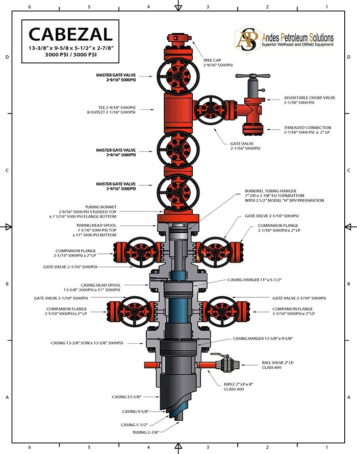
The term Header is defined, in industry as all permanent equipment between the upper portion of the surface cladding and the adapter flange (adapter flange). The flow section (christmas tree) or Christmas tree is defined as the permanent equipment above the adapter flange (valves and meters); however, for this case, the flow section will be taken as a component part of the head.
He head is the end point where the concentric strings of coatings and Production pipes reach the surface. That collection of valves, hangers and packing elements is known as the head, head of the well or "Tree of Christmas". It can also be used for stimulation treatments, fluids of circulation or other emergencies that may arise during the life of the well.
The head is a element that provides a safe and adequate means to hold and attach the "control of thrusts during drilling "and later supplies a seal between the different strings of coating, and finally a connection for the Christmas tree that controls the Fluid flow from the well.
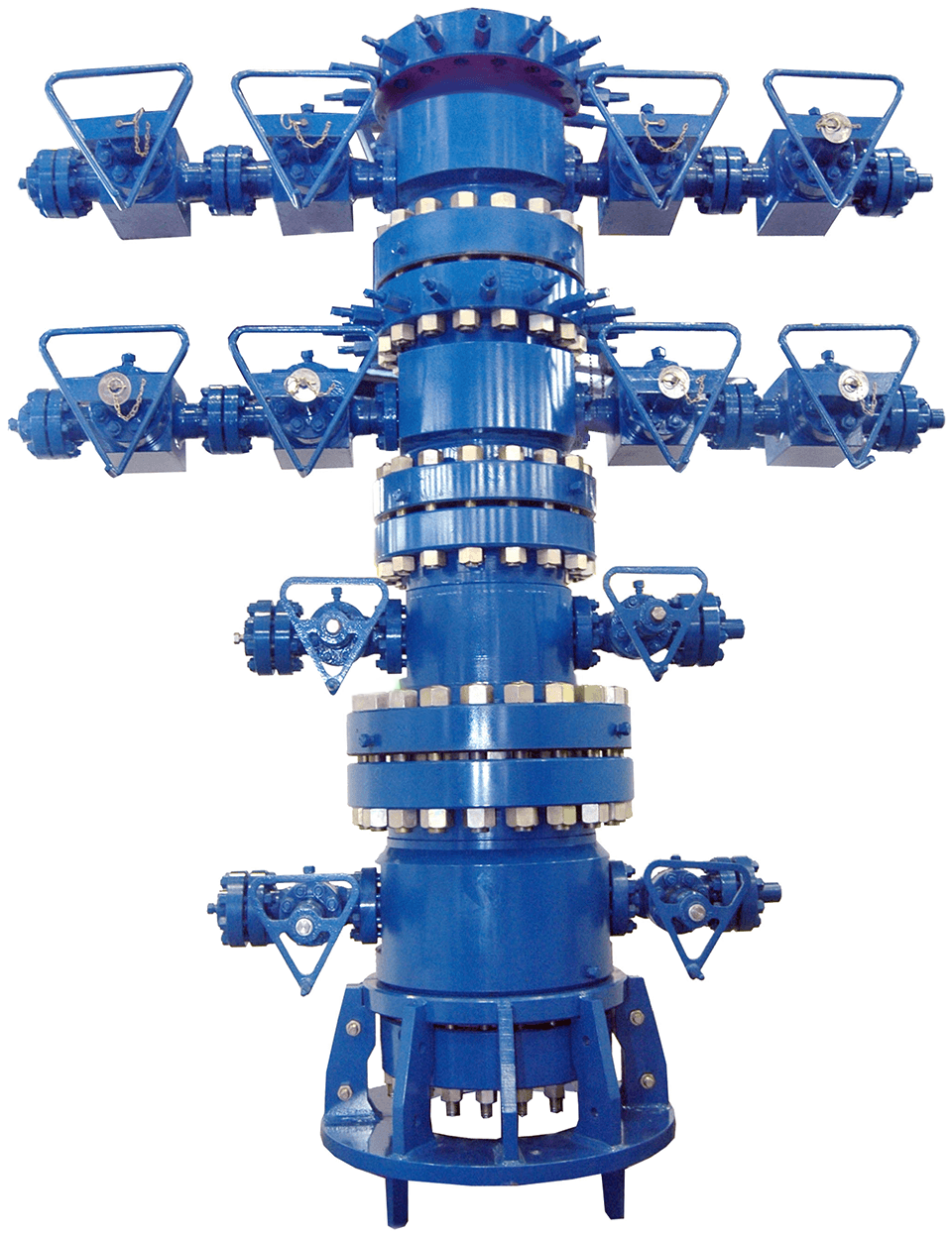
In turn, the head can also be divided into two parts:
A. Drilling equipment.
It usually includes the casing head, casing spool and casing hanger, including the isolation seals, when the previous elements require it. These components are associated with all the coating strings prior to the production coating.
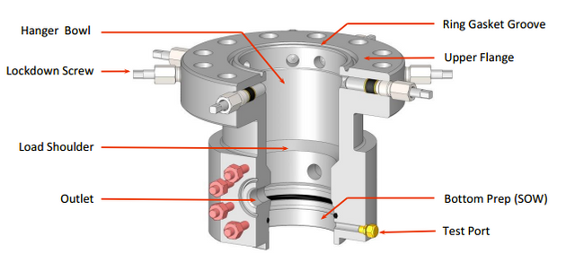
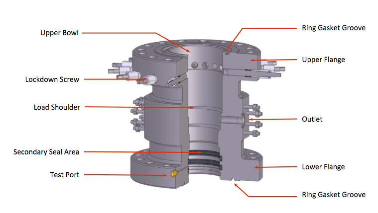
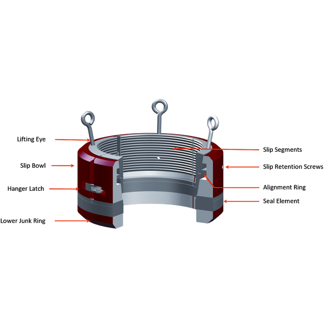
B. Completion equipment:
Includes as main components; Tubing head, Tubing hanger, Tubing head adapter, christmas tree, valves, crosses and tee and chock. In general all the elements associated with the production coating and the production pipe used; to complete and produce the well including the flow control equipment.
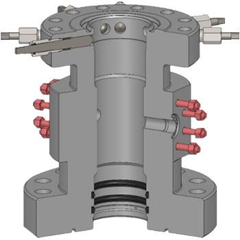
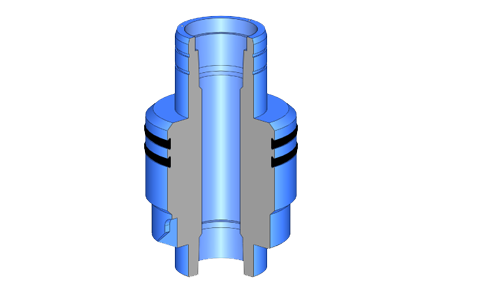
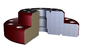.jpg)
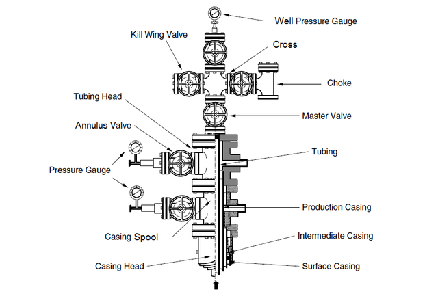
Description of the basic components of the head
A. Primary head of the coating. (Casing heads)
It serves as an intermediate connection between the conductive coating or surface coating and the well control equipment or with the next string and / or the subsequent section (casing spool or Tubing spool). The basic functions of the casing head are to support the casing string, connect or adapt the well control equipment by isolating the hole in the atmosphere and allow access to the hole to control the pressure or return of fluids during drilling operations.
B. Coating hangers. (casing hangers)
They are retainer mechanisms with packages that allow to support, center and usually seal the annular between the lining and the inner bowl of the casing head. There are three classes: wedges, wedge hanger and mandrel type.
C. Test protector. (Protective test)
It has double function according to the design of the selected hanger:
- As a primary Packoff to seal the annular between the casing head bowl and the casing string.
- As a test protector when the hanger has a seal mechanism and its function is to isolate the load area of the wedges that support the string avoiding a hydraulic overpressure.
D. Seals of insulation. (isolated seals)
Under this term is included any type of mechanism that seals the external diameter of the end of the coating string against the lower bowl that by design has the Tubing head or the casing spool that is installed immediately and constitutes the next section.
E. Connection seals. (ring gasket)
Also known as compression rings, they supply a seal
hermetic between two sections or assembled elements.
F. Adapter flanges. (adapter flange or Tubing bonnets)
They allow to connect the last section of the head to the valve assembly that is known as a Christmas tree.
Christmas Tree
The term Head is defined, in the industry as all the permanent equipment between the upper portion of the surface coating and the adapter flange (adapter flange), however usually attributed other colloquial names such as "Christmas tree" or "Cross of the well" . The flow section (christmas tree) or Christmas tree is defined as the permanent equipment above the adapter flange (valves and meters); however, for this case, the flow section will be taken as a component part of the head. It is also recognized by the name of Cruz de pozo, due to the way it resembles.
The purpose of the Christmas Tree (Xmas Tree) is to provide a valve control of the fluids produced or injected into the well. The Xmas Tree is normally flanged to the well head system after running the production tubing. The design shown is one of the simplest and most common designs, it can be seen briefly that it comprises 2 lateral outlet valves, normally one for production and another for injection. Additionally, a third outlet valve provides vertical access to the tubing by means of concentric cable tools or coiled tubing tools.
Types of heads
The pressure, temperature and type of fluids to be handled, as well as the method of completion-production, environment and depth, are the factors that determine the type of head that must be installed in a well.
Conventional Production Head
This type of head is used for wells with depths no greater than 14000 ft (feet), in which it is not expected to handle undesirable components (Acid Sulfuric (H2 S), Carbon Dioxide (CO2), etc.) and where the working pressures do not They surpass 5000 psi (pounds per square inch). These heads are used in wells that will be finished in relatively shallow reservoirs, and the same they allow to produce in natural flow or in artificial lift and to carry out works of stimulation (sand forcings, fractures, acidification, etc ...), where the ring Production can be pressurized up to a pressure not higher than 2000 psi.
Thermal Production Head
They are heads that are used in wells subjected to steam injection and where temperatures of up to ± 650 ° F are reached. Structurally, they are similar to conventional production head, with the difference that the body itself, and its
components are manufactured with material resistant to high temperatures.
Deep Well Head
As the name implies, it is the type of head that is used in wells withdepths greater than 14,000 ft, to be completed in reservoirs with high Pressure. They are designed to handle pressures of up to 15,000 psi and components highly corrosive like CO2 and H2 S. They differ from the heads conventional, because they consist of an additional section, which serves to hang the intermediate coating.
Sections of a Head
The conventional and thermal heads are made up of four sections (A, B, C, D), each of which fulfills a specific function that is Define below:
Section "A" or Production Coating Head
This section is the first one that is installed, after running the lining of surface. It can be welded or screwed to said lining. This formed by the flange of the surface coating and, generally, by two valves laterals, which allow the entry or exit of fluids through the annular of surface. In its internal part, this section has a profile where the hanger sits or Onion production lining, and on the face of the flange have a channel where the ring that makes the metal-metal seal between the flange of the surface coating and the lower flange of the head of the production pipeline.
Shoehorn or Production Coating Onion It is a conical or cylindrical element that sits on the profile of the head of the production lining, and its function is to support the weight of the string of the coating and, at the same time, isolate the annular surface. It is known as "seal primary".
Sección “B”
It is known; as head of the production or injection pipe. Is a carreto with two flanges. Usually, the lower one is larger in diameter than the upper one.
Additionally, it has two side ports with their respective 2 "valves, which allow the exit and entry of fluids through the production annular and where it goes connected the lifting gas injection line. In its lower part
internally, it has a set of packings that form the "secondary seal". Inside it comes to insert the tab of the production liner. This Packing expands horizontally and serves to seal any communication between both coatings or between the production and the inner part of the head. Internally, this head has a seat or profile where the onion is placed or hanger of the production or injection pipe. This serves as a seal between the pipe of production, and the annular of production. This void limits or forms the wall internal coating of production.
Section C"
This is the so-called top section of the head. It is the third part, which is formed by the adapter and the master valve.
The adapter is the component that serves as a link between the upper flange of the head of the pipe and the lower flange of the master valve. This valve serves to control the flow through the pipe, or close the well, and its internal diameter must be greater than or equal to that of the production or injection pipe. It is the most valve of the head and according to the characteristics of the well, sometimes place two master valves in series, as for example, in the injection wells Of gas.
Section "d"
It is the last part of the head, also called cross of the well or tree of Christmas, and starts from the top flange of the master valve. This section has as components: the flow cross, two "Z" side valves, which end In the pockets of the reducer, there they are connected to the production or flow line and to the crown valve, which ends in a flange with a blind plug. This valve crowns it must have a diameter greater than or equal to that of the master valve. 28 For deep wells, the components of a head are basically those mentioned, with the exception that they have an additional section that serves to hang the intermediate covering and the side valves that communicate to the annular between the intermediate and surface coating.
Security system
The first security system that was used in the oil fields It consisted of a cannon from the time of the Civil War of the United States, which kept charged and pointed to the storage tanks. In case of fire, pulled the barrel to open a hole in the tank that was burning, in order to empty it and drain the oil away from the other tanks. Today the systems of 31
security are considered as important as human lives and the environment protection, not to mention the conservation of oil and gas that each day are more precious.
The uncontrolled flow of an oil or gas well, that is, the blowout, It can cause a catastrophe of great dimension.
The first security system that was used in the oil fields. As for the stage of the well drilling, it is sometimes known that
There are some conditions that could cause a blowout, and in that case, It is usually possible to avoid it. Even when there are unknown conditions that could favor their occurrence, the skills and expertise of the staff and the use of
Appropriate safety equipment usually prevents such emergencies. In spite of This, the blowouts still occur sporadically during the drilling of wells. In almost all cases, the blowout or the possibility of a blowout occurs
by a combination of factors, such as the following:
- Incidental cases (hurricane, flood, earthquake, etc.)
- Failure of controls or equipment on the surface
- Fire or explosion that causes the failure of a control device in the surface
- Sabotage
- Human error
- Shocks, such as those that occur between boats and the head of a well Marine
- Lack of adequate safety equipment.
It consisted of a cannon from the time of the Civil War of the United States, which kept charged and pointed to the storage tanks . In case of fire, pulled the barrel to open a hole in the tank that was burning, in order to empty it and drain the oil away from the other tanks. Today the systems of 31 security are considered as important as human lives and the environment protection, not to mention the conservation of oil and gas that each day are more precious.
The uncontrolled flow of an oil or gas well, that is, the blowout, It can cause a catastrophe of great dimension.
All direct drive valves (by flow rate) depend on an increase in the flow velocity, or a pressure drop in the valve, to effect closure. A total lack of control devices in the 32 surface almost always allows the development of one of these conditions. Other Situations that can develop and prevent the closing of the valve are:
Depletion of the petroleum deposit, after calibration and installation of the valve, prevents the flow velocity from reaching the closing regulation there of The productive zone may be partially obstructed by sand, or production pipes can be partially plugged with paraffin over the valve, so it can not reach its regulation closing When insufficient data are used in the calculations of the well or bad quality, these cause an incorrect calibration, to the point that the well never reaches the flow rate used in the calibration of the valve Control devices on the surface may be damaged, without being totally destroyed This maintains a flow velocity lower than the closing regulation of the valve.
To overcome these disadvantages or potential problems, it was developed near the 1950 a safety valve controlled from the surface. It was provided with a Large flow channel, remote opening and closing control, and ability to be
regulated to operate in a wide variety of abnormal conditions (fire, break of the control or flow line, etc).
Because of the higher cost and difficulties in manufacturing this valve in the United States of America, there was no immediate demand for them, except abroad. Therefore, its use increased only gradually until the end of the sixties, when its advantages, compared with those of the valves of direct drive, they became more important for producers
Americans The rapid increase in demand and in use, after that At the moment, they have been a phenomenon. The good general acceptance of the valve "subsurface" security controlled from the surface, had an important effect on the security systems used in marine platforms. This is because valve is kept open by hydraulic pressure supplied by a system of control, and is especially adaptable to the automatic drive in a way that it was not possible in the case of valves controlled directly by the flow in the water well. In fact, it opened the way to very advanced systems for closing
emergency, as they are currently required.
The adaptability of this valve allows its use, both in multiple situations specialized as in common security applications:
- In deep wells or located in deep water or in regions permanently frozen. In these cases, they are often used
two control lines to maintain hydrostatic pressure balance in the control lines - Underwater test tree. During the productivity tests performed on a boat, it is preferred to have a master valve on the tree, for security reasons
- Some wells with artificial lift require valves subsurface security. These can be triggered by pressure hydraulic, by hydraulic pump, by electric pump, or by the pressure of a "gas lift" system.
I hope this publication has pleased you, in another opportunity I will be deepening more in the subject, since the subject of the drilling of oil grounds is extensive and counts on a very large amount of material, for example in another opportunity I would be talking about what is refers to the different valves that are used in the flow sections, heads and crosses. To all who read this post, I thank you.
For more information visit these pages:
https://prezi.com/nh2zgssyntda/well-heads-cabezal-de-pozo/
http://larocamadrehg.blogspot.com/2013/
http://sentrywellhead.com/products/tubing-heads/
Congratulations @jorge150785! You received a personal award!
Click here to view your Board of Honor
Congratulations @jorge150785! You received a personal award!
You can view your badges on your Steem Board and compare to others on the Steem Ranking
Vote for @Steemitboard as a witness to get one more award and increased upvotes!