THE PHYSICS BEHIND CHARGE AND FIELD: Electrical Potential, Capacitors and The Coulomb's Law.
In using a flame probe for investigating the potential between two parallel plates, a voltmeter is used to measure the p.d. across the parallel plates. A flame probe is used to measure voltage at points in the space between the plates; the voltage increases as the probe is moved from the left plate, which is at 0 V, to the right plate. More precisely, the probe measures a voltage in the field between the plates. This voltage is called the electric potential. The potential can be defined as the p.d. between the plate at 0 V (or zero potential) and the probe.
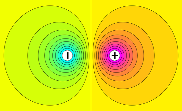
When the probe is moved parallel to the plates the potential remains the same: The probe is moving along an equipotential, that is, a plane of equal voltage or potential. The equipotentials are always at right angles to the field lines. Notice that at the edges of the plates where the field is no longer uniform, the equipotentials are still perpendicular to the field lines. The potential changes gradually in a uniform field. In a graph of potential against distance between the plates. The plot shows that the potential gradient is constant and negative. Thus, where r is the distance, the field strength (the force on unit charge) is given by the equation:
Field strength = -(potential gradient)
E = -dV/dr
Although this relationship has been derived for a uniform field, we shall see later that it is true for all fields.

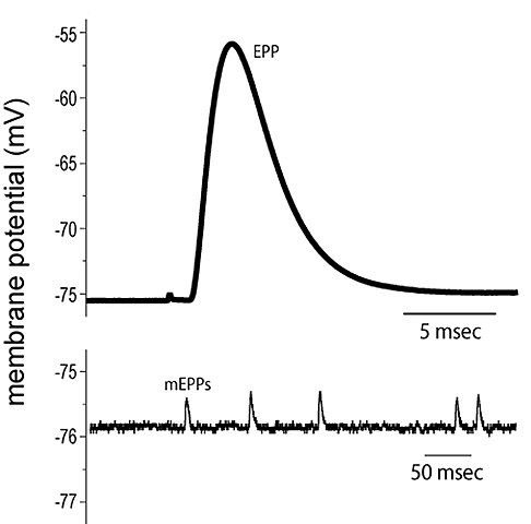
Potential graph. Meriney, CC BY-SA 4.0
NON-UNIFORM FIELDS
In non-uniform fields the potential gradient varies. In the electric field below a thundercloud. Notice how the potential gradient increases around the pointed church spire. The pointed spire distorts the pattern, making the field stronger around the point.
This property is used in a lightning conductor, which is basically a pointed metal rod. One end is earthed and the pointed end extends above the top of the building to which it is attached. A thundercloud often has a concentration of negative charge at its base. This generates an electric field between the base and the ground. Below the thundercloud, the field at the point of the lightning conductor is strong enough to ionize air molecules around the point.
The resulting charged molecules – ions – move in the field: positive ions go towards the cloud base and electrons go to earth through the lightning conductor. This mechanism allows the thundercloud to discharge slowly before enough charge builds up to cause lightning.
Electrostatic paint spraying
Particles of paint are given a positive charge as they leave the nozzle of a spray gun. The object to be painted is earthed so that there is an electric field between the nozzle and the object. The charged paint droplets follow the field lines and are deposited evenly over the surface of the object
PARALLEL PLATE CAPACITOR
So far, I have been looking at the electric field between two parallel plates. This arrangement can in fact store electric charge, which makes it a capacitor. We have seen that the field between the capacitor plates depends upon the p.d across them and the distance between them. Let us now look at other factors that affect the strength of a field.
There is a p.d. across the plates when they are charged. In fact, the charge on the plates is proportional to the p.d. (Q = CV). The quantity of charge on the plates also depends on the area of the plates. If the area of the plates is doubled, the quantity of charge the capacitor can store is doubled. So:
Q α A
The ratio of charge to area (Q/A) is called the charge density (σ). Since the charge density is proportional to p.d., it is proportional to the field strength:
charge density α field strength
σ α E
Q/A α V/d
There is one other factor that affects the field strength. This is the medium between the plates, the dielectric. The dielectric is an insulator, the simplest being a vacuum. Often, the insulating material is air, oil or paper. For a vacuum between the plates:
Q/A = ε0 V/d
Where ε0 is a constant called the permittivity of free space (or of a vacuum) which links charge density and field strength. Its units are farads per metre and it tells us how good a vacuum is at allowing an electric field to be established. The farad, symbol F, is the unit of capacitance: a 1 farad capacitor charged by a p.d of 1 volt carries a charge of 1 coulomb. In practise, capacitors have much smaller values, ranging between microfarads and picofarads.
The value of ε0 is 8.85 × 10⁻¹² Fm-1, or alternatively 8.85 × 10⁻¹² C2 N-1 m-2.
Another way of arranging the equation gives expressions for capacitance, Symbol C:
C = Q/V = ε0 A/d
The second line of the equation gives the capacitance in terms of the physical dimensions of the dielectric medium and the capacitor. In practice, different dielectric materials are used for capacitors, depending on their size.
The equation for the capacitance is slightly modified to account for the dielectric:
C = ε0 εr A/d
Where εr is called the relative permittivity of the dielectric used. The plates of a capacitor are covered with a ‘blanket’ of charge. The charge spreads out evenly over most of the plates – only at the edges is the distribution more uneven with more charge concentrated at any ‘sharp’ edges and corners.

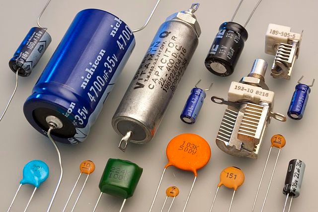
Capacitors. Eric Schrader, CC BY S.A 2.0
PRACTICAL CAPACITORS
There are many different types of capacitor available, made from different materials and suitable for different applications. They come in a range of shapes and sizes, in values from picofarads up to farads. Capacitors are used to store charge (and energy), to ‘smooth’ a fluctuating voltage or to allow high frequency signals to ‘bypass’ parts of a circuit. They are essential in circuits designed to respond to certain frequencies. Examples are the ‘tuned circuit’ in radio receivers used to select a signal of a particular frequency, and ‘filters’ which use the fact that the behaviour of a capacitor in a.c. circuits depends on frequency. With accurate capacitors, filters will respond to very narrow bands of signal frequencies, which can be either filtered out or allowed to pass.
Sometimes very accurate capacitors are needed, usually of low value,typically pF or nF. Capacitors of very high value are used, such as in ‘smoothing’, where accuracy is not important. All capacitors lose charge over time, that is, they ‘leak’. Most capacitors have a fixed value, but others vary over a range of values, as in tuned circuits. The table below shows some of the common types of capacitor that are used.
| Type | Capacitance range | Maximum voltage | Accuracy | Leakage |
| Mica | 1 pF-10 nF | 100-600 V | Good | Very useful at radio frequencies |
| Ceramic | 10 pF-1 uF | 50-30 000 V | Poor | cheap, small |
| Polystyrene | 10 pF-2.7 µF | 100-600 V | Excellent | High quality, used in accurate filters |
| polycarbonate | 100 pF-30 pF | 50-800 V | Excellent | High quality, small |
| Tantalum | 100 nF-500 µF | 6-100 V | Poor | High capacitance, polarised |
| Electrolytic (aluminium) | 100 nF-2 F | 3-600 V | Horrible | Smoothing power supply filters, polarised |
EFFECT OF THE DIELECTRIC
Placing an insulating material between the plates of a capacitor increases the capacitance. That means that more charge can be stored for the same voltage across the plates, and this effect is greater when materials with greater values of εr are used.
NON-UNIFORM ELECTRIC FIELD – COULOMB’S LAW
In 1785, Coulomb measured the forces between small charged bodies and summarised his results in the form of an equation that is now known as Coulomb’s law. He discovered that force F depends on the size of the charges Q1 and Q2 on the bodies, and on the distance r between them. As the distance increases, the force decreases – in fact, if the distance doubles, the force decreases by a factor of four. That is, the force obeys an inverse square law:
F = k Q1Q2/r2
where k is constant.
This equation is almost identical in form to Newton’s law of gravitation:
F = -G m1m2/r2
Unlike gravity, which is always attractive, the electric force can be either attractive or repulsive: when the charges are opposite, the force is attractive and defined as negative, like gravity; when the charges are of the same sign, the force is repulsive and defined as positive.
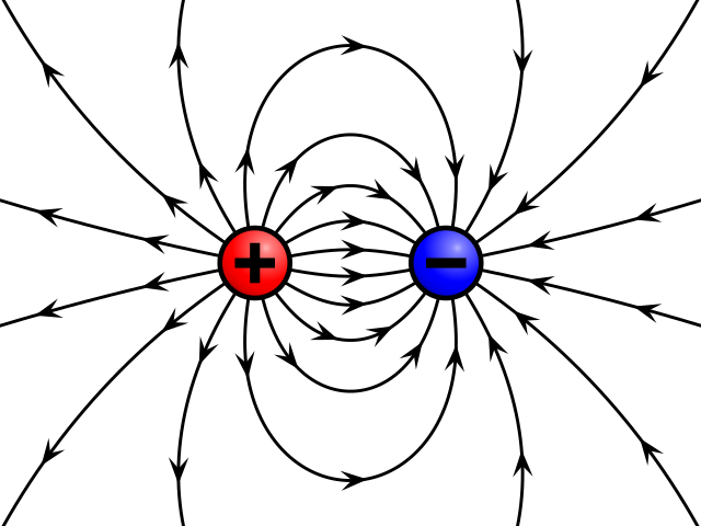
The figure below shows the field around an isolated charge. This is a two-dimensional representation, but the field around the charge is three-dimensional. The field lines spread out radially from the centre. Yet again, this ‘map’ of field lines helps us visualise the field, but it is limited. It is very difficult to show on such a ‘map’ the precise way that the magnitude of the field changes. The equations below help solve this problem.

Field of a positive and a negative point charge. Geek3, CC BY-SA 3.0
FIELD STRENGTH
The strength E of the electric field can be measured by considering the force on a second ‘test’ charge, Q2, at a distance r from a charge Q1:
Field strength = force per unit charge
= (k Q1Q2/r2) ÷ Q2
E = k Q1/r2
That is, the field strength in a non-uniform electric field also obeys the inverse Square law.
EXAMPLE
The electric field strength 50 cm from the centre of a small charged sphere is 18 NC-1. Calculate the charge on the sphere. (k = 9 × 10⁹ Nm2 C-2)
ANSWER: The field strength is:
E = k Q/r2= 18 NC-1
Rearranging:
Q = Er2/k = 18 × ( 5 × 10⁻¹)2 / 9 × 109
= 18 × 25 × 10-2/9 × 109
= 5 × 10⁻¹⁰ C
POTENTIAL IN A RADIAL FIELD
The flame probe used to investigate the potential between parallel plates was described earlier. It can also be used to investigate the way electrical potential varies around an isolated charged body, in this case a sphere. The potential decreases, but it follows a 1/r law
The potential again depends on the charge:
V = k Q1/r
The constant k can be found by considering an isolated charged sphere. In such a sphere, with radius r, carrying a charge of Q coulombs. We know that:
Charge density = ε0 × field strength
Q/A = ε0 kQ/r2
Where A = 4πr², the area of the sphere. Therefore we have:
Q/4πr² = ε0 kQ/r2
The charge and radius squared cancel, leaving us with:
k = 1/4πε0
RELATIONSHIP BETWEEN FIELD AND POTENTIAL
Earlier in this post, I showed that for a uniform field the field strength E was equal to minus the potential gradient:
E = -dV/dr
The same is still true for fields that vary by an inverse square law.
I can show this mathematically:
V = 1/4πε0 × Q/rE = -dV/dr= - Q/4πε0 × d(1/r)/drTherefore:E = 1/4πε0 (Q/r2)
This means that the slope of the potential-distance graph gives the value of the field strength at that point.
SUMMARY
By the end of this post and the [previous one] you should know and understand the following:
.The field between charged plates is uniform and the electric field strength is the force per unit charge measured in newtons per coulomb.
.The equations for uniform fields are E = F/Q = V/d and the work done in moving a charge of Q coulombs through a p.d. of V volts is QV joules.
.The kinetic energy of an electron emerging from an electron gun is given by mv2 = eV and the electronvolt is the energy gained by a particle carrying a charge of 1.6 × 10⁻¹⁹ coulombs when it has been accelerated through a p.d. of 1 V.
.The potential at a point in an electric ficld is the work done per coulomb in moving a unit charge from zero or earth potential to that point. Equipotentials can be thought of as surfaces in space of equal potential which cut electric field lines at right angles.
.Field strength E is equal to (minus) the potential gradient, -dV/dr. Charge density = permittivity × field strength of free space, and capacitance C = ε0A/d and the force between two charges is given by Coulomb’s law, F = k Q1Q2/r2 and field strength E = kQ/r2, where k = 1/4πε0 and the potential around a charge Q is given by V = kQ/r.
REFERENCES
https://en.wikipedia.org/wiki/Equipotential
http://physics.bu.edu/~duffy/semester2/c05_potential.html
https://courses.lumenlearning.com/physics/chapter/19-4-equipotential-lines/
http://spiff.rit.edu/classes/phys213/lectures/equipot/equipot_long.html
https://www.science.gov/topicpages/n/non-uniform+electric+field
https://en.wikipedia.org/wiki/Electrostatic_coating
https://www.superiorglove.com/blog/electrostatic-spray-painting
https://www.electronics-tutorials.ws/capacitor/cap_1.html
http://hyperphysics.phy-astr.gsu.edu/hbase/electric/pplate.html
https://www.electronics-notes.com/articles/electronic_components/capacitors/capacitor-uses.php
https://www.electronics-tutorials.ws/capacitor/cap_2.html
https://en.wikipedia.org/wiki/Applications_of_capacitors
https://en.wikipedia.org/wiki/Capacitor
https://en.wikibooks.org/wiki/Practical_Electronics/Capacitors
https://courses.lumenlearning.com/boundless-physics/chapter/electric-flux-and-gausss-law/
http://www.physics.usyd.edu.au/super/life_sciences/E/E-all.pdf
http://web.mit.edu/8.02t/www/802TEAL3D/visualizations/coursenotes/modules/guide02.pdf
https://www.physicsclassroom.com/class/estatics/Lesson-4/Electric-Field-Intensity

Congratulations @emperorhassy! You have completed the following achievement on the Steem blockchain and have been rewarded with new badge(s) :
You can view your badges on your Steem Board and compare to others on the Steem Ranking
If you no longer want to receive notifications, reply to this comment with the word
STOPDo not miss the last post from @steemitboard:
@tipu curate
Upvoted 👌 (Mana: 15/25 - need recharge?)
This post has been voted on by the SteemSTEM curation team and voting trail. It is elligible for support from @curie and @minnowbooster.
If you appreciate the work we are doing, then consider supporting our witness @stem.witness. Additional witness support to the curie witness would be appreciated as well.
For additional information please join us on the SteemSTEM discord and to get to know the rest of the community!
Thanks for having used the steemstem.io app and included @steemstem in the list of beneficiaries of this post. This granted you a stronger support from SteemSTEM.