An Introduction to PLC (Programmable Logic Controller) for Beginners
An Overview of Programmable Logic Controller
.jpg)
Numerous types of PLCs from a vast number of manufacturers are available in today’s market. Programmable Logic Controller (PLC), also known as Industrial Computer is the main component in today’s industrial automation sector. It is a specialized electronic device operated in many industries to monitor and control machines, building systems, and production processes. Logic controllers are generally tasked with monitoring and controlling a very large number of sensors and actuators, and are so diverse from other computer systems when it comes to their extensive input/output (I/O) arrangements.
Every PLC is designed to execute a single set of tasks, except under real-time constraints and with superior reliability and performance, and it shares common terms with typical PCs like central processing unit, memory, software, and communications. It is designed to be extremely robust to survive in a rugged industrial atmosphere and to be very flexible in how it interfaces with inputs and outputs to the real world. It is surely capable of withstanding extreme temperatures, humidity, vibration, and electrical noise and built with remarkable functional features like PID controllers, sequential control, timers and counters, the simplicity of programming, consistent controlling capabilities and improved hardware usage.
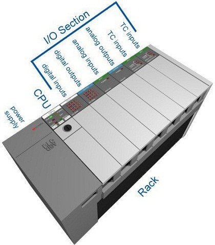
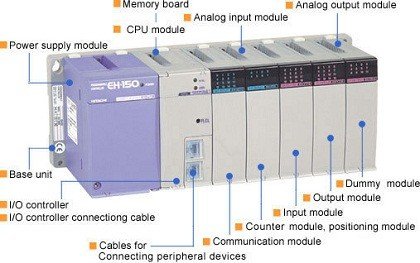
The mechanisms that make a PLC work can be divided into three core areas.
- The power supply and rack
- The central processing unit (CPU)
- The input/output (I/O) section
PLC Core Areas
The Rack and Power Supply
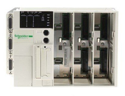
The rack is the component that clamps everything together and can be purchased in different sizes to hold more modules varying on the requirements of the control system. It has a backplane at the rear which all the modules like CPU and other I/O modules are attached to the corresponding slots, allowing the communication amongst CPU and I/O modules to send or receive the data. This communication is established by addressing the I/O modules according to the location from CPU module along the bus. Particular buses provide essential power to I/O module circuitry, but then again they do not supply any power to sensors and actuators connected to I/O modules.
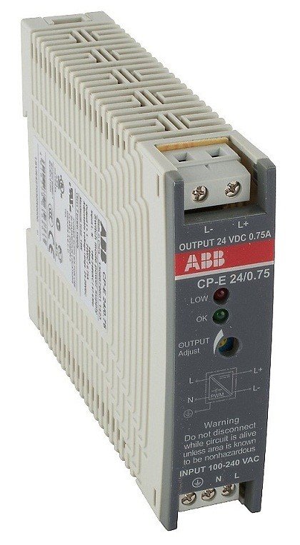
This module fastened into the rack as well supplies the necessary regulated DC power for the whole system by converting the available AC power to DC power required for CPU and I/O modules plugged into the rack. The output 5V DC energies the computer circuitry, and in some PLC’s 24DC on the bus rack powers few sensors and actuators. The most widely used power supplies operate with 120 VAC or 24 VDC sources.
CPU Module
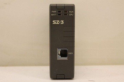
CPU module is the brain of the whole PLC characteristically lives in the slot beside the power supply. It finalizes the three processes:
• Execute the Control Instructions comprised of the User's Programs. This program is accumulated in "nonvolatile" memory, which implicates that the program will not be lost if power is eliminated.
• Communicate with other devices, which can consist of I/O Devices, Programming Devices, Networks, and even other PLCs.
• Implement Housekeeping activities such as Communications, Internal Diagnostics, etc.
The CPU module comprises of a microprocessor which is in control for doing all the necessary computations and data processing by receiving the inputs and generating appropriate outputs; memory chip consists of both ROM and RAM memories; and other integrated circuits to control logic, monitoring, and communications. The ROM memory encompasses the operating system, driver, and application programs, whereas the RAM accumulates user-written programs and working data.

When the power supply breaks or stop working, these PLCs utilize retentive memory to save user programs and data and to carry on the implementation of a user program once the power is reestablished, without the use of a keyboard or monitor for reprograming the processor each time. The retentive memory can be executed with the use of long-life batteries, EEPROM modules, and flash memory techniques.
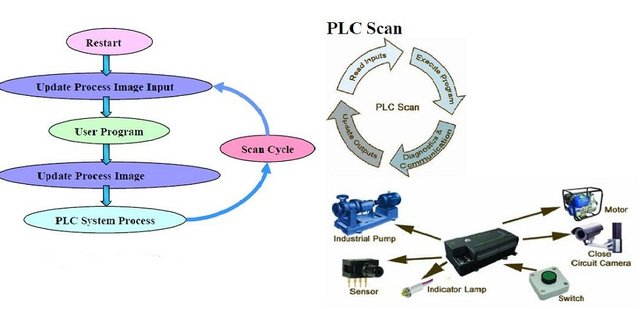
Since a PLC is a dedicated controller, it will only operate this one program over and over again. One cycle over and done with the program is known as a scan time and consists of reading the inputs from the other modules, executing the logic based on these inputs and then updated the outputs consequently. In the range of 1/1000th of a second, the scan time happens rapidly. The memory in the CPU stores the program while also holding the status of the I/O and is responsible for a means to store values.
Manufacturers offer different types of CPUs based on the complexity needed for the system.
The CPU has different operating modes:
• programming mode - it accepts the downloaded logic from a PC.
• run mode - it can execute the program and operate the process.
I/O System
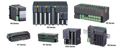
I/O system provides the physical connection between the equipment and the PLC allowing the connection of the sensors and actuators to the system to sense or control the real-time variables such as temperature, pressure flow, and other designated variables. Opening the doors on an I/O card reveals a terminal strip where the devices connect.
It is just simply an importance of knowing what inputs and outputs are needed, plugging the rack with the appropriate cards and then addressing them correctly in the CPUs program then everything will operate according to your desired output.
I/O modules vary in type, range, and capabilities and particularly include:
Digital I/O module - used to connect the sensors and actuator that are of digital in nature, i.e., only for switch ON and OFF purpose. These modules are available on both AC and DC voltages and currents with the variable number of digital inputs and outputs.
Analog I/O modules - used to connect the sensors and actuators that provide the analog electric signals. Inside these modules, analog to digital converter is used to convert the analog to processor understandable data, i.e., digital data. This module’s number of channel’s availability is also can be modified depending on its function.
Communication Interface Modules - are intelligent I/O modules that exchange the information between a CPU and communication network. These are applicable for communicating with other PLCs and computers that are positioned at an inaccessible or far away distance.
How Does a PLC Operate?
1.) Input Scan - detects the state of all input devices that are connected to the PLC
2.) Program Scan- executes the user created program logic
3.) Output Scan - energizes or de-energize all output devices that are connected to the PLC
4.) Housekeeping - includes communications with programming terminals, internal diagnostics, and others.
What Are INPUT/OUTPUT Devices?
The figure below shows the overall operation of the elements we've tackled above and a glimpse to some input/output representation.
PLC ACRONYMS
The following table shows a list of commonly used Acronyms that you see when researching or using your PLC.
ASCII      American Standard Code for Information Interchange
BCD        Binary Coded Decimal
CSA        Canadian Standards Association
DIO        Distributed I/O
EIA        Electronic Industries Association
EMI        Electromagnetic Interference
HMI        Human Machine Interface
IEC        International Electrotechnical Commission
IEEE       Institute of Electrical and Electronic Engineers
I/O        Input(s) and/or Output(s)
ISO        International Standards Organization
LL         Ladder Logic
LSB        Least Significant Bit
MMI        Man-Machine Interface
MODICON    Modular Digital Controller
MSB        Most Significant Bit
PID        Proportional Integral Derivative (feedback control)
RF         Radio Frequency
RIO        Remote I/O
RTU        Remote Terminal Unit
SCADA      Supervisory Control And Data Acquisition
TCP/IP     Transmission Control Protocol / Internet Protocol
PLC Typical Instructions
Be mindful that particular terminology and operational specifics differ usually among PLC manufacturers, and time and again implementation details change from generation to generation. Often the hardest part, specifically for an inexperienced PLC programmer, is performing the mental ju-jitsu essential to retain the jargon straight from the manufacturer to manufacturer.
Positive Logic (most PLCs follow this convention)
True = logic 1 = input energized.
False = logic 0 = input NOT energized.
Negative Logic
True = logic 0 = input NOT energized
False = logic 1 = input energized.
Normally Open
(XIC) - eXamine If Closed.
This instruction is true (logic 1) when the hardware input (or internal relay equivalent) is energized.
Normally Closed
(XIO) - eXamine If Open.
This instruction is true (logic 1) when the hardware input (or internal relay equivalent) is NOT energized.
Output Enable
(OTE) - OuTput Enable.
This instruction mimics the action of a conventional relay coil.
On Timer
(TON) - Timer ON
Generally, ON timers begin timing when the input (enable) line goes true, and reset if the enable line goes false before setpoint has been reached. If enabled until setpoint is reached then the timer output goes true and stays true until the input (enable) line goes false.
Off Timer
(TOF) - Timer OFF.
Generally, OFF timers begin timing on a true-to-false transition and continue timing as long as the preceding logic remains false. When the accumulated time equals setpoint the TOF output goes ON and stays ON until the rung goes true.
Retentive Timer
(RTO) - Retentive Timer On.
This kind of timer does NOT reset the accumulated time when the input condition becomes false.
Relatively, it retains the last accumulated time in memory, and if or when the input goes true again, resumes timing starting that point. In the Allen-Bradley construction, this instruction becomes true as soon as the set point (preset) time has been reached, and remains true while waiting for a RES (RESet) instruction is attained true to clear it.
Latching Relays
(OTL) - OuTput Latch.
(OTU) - OuTput Unlatch.
Mostly, the unlatch operator takes priority. To be exact, if the unlatch instruction is true then the relay output is false even if the latch instruction may also be true. In Allen-Bradley ladder logic, latch and unlatch relays are distinct operators.
On the other hand, other ladder dialects choose for a single operator modeled after RS (Reset-Set) flip-flop IC chip logic.
Jump to Subroutine
(JSR) - Jump to SubRoutine
For jumping from one rung to another the JSR (Jump to Subroutine) command is used.
And this would be the end for this topic, just a glimpse to the basic definition, operation, elements, and instructions of a Programmable Logic Controller and rest assured for the next topic, few examples for certain programs will be given.
Excelent Post, congratulations
thanks @grgmm :) there are only a few who could appreciate PLC stuffs :)