Introduction to 3D parametric modeling - Part II
Hello everyone!
In the first part of this article, Introduction to 3D parametric modeling - Part I - that I posted yesterday - you find a description and the definition of 3D parametric modeling, I explained how it works and its advantages; I also mentioned its "basic components": features and parameters.
Today I will go into detail about these basic components and I'll try to clearly answer the following questions:
- What are the features and why are they so important?
- What are the parameters and what are they used for?
What are parameters and features?
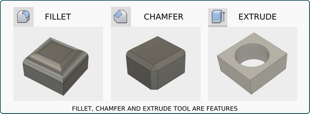
Let's start with features: they are the basic elements for parametric modeling, as they are all the possible operations available in the modeling environment, from the four main operations (extrude, revolve, sweep and loft), to holes, fillets, chamfers, shells and so on. Each solid body and/or surface is created through a series of subsequent modeling operations or “features”, that's why 3D parametric modeling is also called “feature-based modeling”.
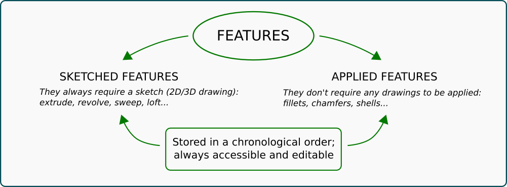
Once we use a feature, the software store it in a chronological order, creating a kind of timeline, telling us the story of our model through the sequence of its features.
Some features require a sketch (that means a 2D/3D drawing), others are applied directly to objects. The first ones are called “sketched features”, here are some examples: extrude, revolve, sweep and loft; the second ones are defined “applied features”, because they don't require any drawings to be applied; among them there are fillets, chamfers and shells.
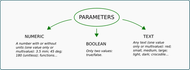
Each feature comes with specific attributes (a diameter, a height, a length, an angle...) which are, indeed, numbers! They are the mathematics hidden behind each object and operation, basic elements for each features and, in a nutshell, what we call parameters. Most diffused parameters are dimensions, but they are not just numbers; some parameters may have boolean – yes/not – or text values; they are all stored in a list that can be easily open for viewing and editing.
Parameters are bidirectionally connected to geometry: they both depends on it and affect it. It means that whenever a change to a solid or a surface is required, we can do so both directly manipulating its geometry and changing its parameter values.
This is a great advantage of parametric modeling and leads to high control and flexibility, everything is easy to change without waste of time (sometimes modeling tools are not even required, it's enough typing new values for some parameters in the list!). In softwares like Autodesk Inventor we can also rename, comment and mark important parameters in the list as “keys” so there is no risk to lose them among the others for future editing.
One last (but not least) consideration: when we model and object using the 3D parametric modeling method, the result is not just an ordinary object, it is an entire class of objects easy to modify; from the first one we can create infinite combinations of parameters which means infinite potential objects of the same kind. That's why parametric modeling is such a great and powerful tool!
I know, that's a lot of theory! But it is extremely important to understand the basics of parametric modeling and its great potential before starting with 3D modeling.
Thanks everyone for reading this post, stay tuned for the next one: it will be about the four basic 3D modeling operations
Note: all images on this article were created by the author, the word cloud at the beginning was created with a free online tool (Wordclouds.com).