Logic Design - Multiplexer, Encoder and Decoder Circuits

Hello I'm back and this time we will talk about more Advanced Circuits! I will start off with Multiplexers, continue with Encoders and finish with Decoders! So, without further do let's get started!
Multiplexers:
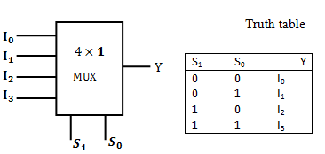
A Multiplexer is a circuit that selects one of 2^n inputs from n selection lines and gives 1 specific Output! A MUX is also called a Data Selector. So, we have 2^n-to-1 Multiplexers, where n is the number of selection lines. For example, MUX 2-to-1, 4-to-1, 8-to-1 etc.
 4-to-1 Mux and Truth Table!
An 4-to-1 mux for example will have 2 Selection Lines and will work for 3 Variable Input!
To define those Inputs we have to know what kind of Outputs we have in every Input combination. So, we will use N-1 of the Inputs Variables as Selection Inputs to define minterm groups and afterwards compare the value of the other Variable (01) with the one of the Outputs of the minterm groups (you will understand it better in a minute). This Comparation will give us our "I" Inputs for the Multiplexer!
Example:
Let's take F(X, Y, Z) for example that has minterms at the binary values of 1, 3, 4, 5.
The Truth Table looks like this:

We will take Y, Z as selections and form groups of 01 for X, where YZ need to be the same (like minterms). So, we will create an array that contains X, the Output F and I that will be the comparition result. Taking the first and fifth row for example we see that only X changes so we have X and F be 01 and so I is X! We continue like this and end up with this:

I0 = X, I1 = 1, I2 = 0 and I3 = X'. That will be the Inputs for our Multiplexer having Y and Z be the Selection Line Inputs! The Output of this 4-to-1 Mux will follow the Truth Table of F(X, Y, Z).
We can do the same using XZ or XY as Selections, again forming groups where the other value changes (01) but the Selections stay the same! We can also use this concept in bigger MUX's with ease.
The Circuit in Multisim can looks like this for example:

You can see that we put X, 1, 0,X' as "I" Inputs and Y, Z as Selections. Having XYZ be 001 (1) we see that the Output becomes 1, because it follows the Truth Table of F!
Encoders:
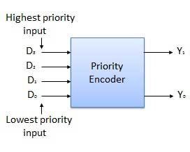
Encoders convert information from one format to another to compress data. In Circuits they compress multiple lines of inputs into a smaller number of outputs! In Encoders the number of Outputs depends on the number of Input "Rows" and they are complicated and need an implementation every time! That's why we mostly use Priority Encoders and those are the ones that I will talk about! In them when having more then 1 Inputs be active at once, the one in the most left has the highest priority and gets selected! The number of Output lines depends on the different Inputs we can have, so we are able of having 4-to-2 , 8-to-3 encoders and so on...that follow the rule of 2^n-to-n Encoder.
 4-to-2 Encoder
We will have to write a Circuit for an Encoder using the Inputs and Outputs of an Truth Table that represents the functionality of such an Encoder!
Example:
Let's take this Truth Table for example that defines an 4-to-2 Encoder:

The X's represent don't cares. We put them cause the most left input has the highest priority on so the value of the others is ignored! You can also see that we have one more Output called Z, whose value tells us if we have an valid Output!
So, to implement this Encoder we will have to write a function that will be translated into a Circuit for each of the Outputs! It's not too difficult in this one!
Using Karnaugh Map for each of those I ended up with this Circuit:

Decoders:
Decoders are the opposite of an Encoder and they actually can also be called Demultiplexers or DEMUX, cause they also work as the opposite of an Multiplexer! The only difference between DEMUX's and Decoders is actually that the first uses only 1 Input and gives us 2^n Outputs, and the second uses n Inputs and gives us 2^n Outputs! I will talk about Decoders to keep things simple, cause DEMUX are more complicated!

As I already said the Decoder is the opposite of an Encoder, so using the Outputs of an Encoder as Inputs in it's corresponding Decoder we get the Inputs that gave us this Outputs in the Encoder! So, we get the Inputs back! But, this is not the way we use them, cause it can be made much simpler!
An Decoder can't have more then 1 Outputs lines have a value of 1! Cause each Output line represents an Combination (binary number) of Inputs. So, each Output line represents an minterm or maxterm of our function! A Decoder mostly has an inverted Output so we will have to use maxterms or use minterms and invert the Outputs using an NAND Gate!
Using that logic we can implement any Circuit, knowing only where it has minterms or maxterms!
Example:
Last time we talked about Full-Adders. Let's implement one using an Decoder! We have to use an 3-to-8 Decoder, cause we have 3 Inputs.
The Truth Table looks like this (if you remember):
To use an Decoder for that Circuit we simply have to put a Multi-Input NAND Gate (if Outputs are inverted, else OR) for each of the Outputs and the Inputs will be the corresponding Outputs the Decoder gives us for each Input Combination (Minterms)!
So, we end up with this Circuit:

This is the end of today's post! Hope you enjoyed it!
Next time we will talk about Clocks and Waveforms, that will help us get into Latches and Flip-Flops that are used in Sequentials Circuits that we will talk about also some posts later on!
Until tomorrow...Bye!