Shader Programming: Massively parallel art [Episode 8: Diffuse Lighting]
Last time, we got the first version of our realtime raymarcher working, and with that we now we have a full 3D engine of our own that we have a lot of fun with.
However, at the moment the output looks distinctly 2D! Let's add some lighting, and you'll see that the object we render is definitely a sphere rather than a circle.
PART 8: Diffuse Lighting
Diffuse lighting is the simplest kind of lighting calculation that we can perform, but will give us decent base lighting for our 3D scenes.
The diffuse lighting calculation takes into account the direction to a light source, and the orientation of the surface. It doesn't depend on the camera position, because diffuse light is reflected equally in all directions.
Here's a diagram to illustrate the idea.
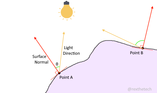
The yellow vectors represent the direction to a lightsource, from two points under consideration, A and B. The red vectors represent the surface normals of the object we are trying to light. It's these surface normal that give us the orientation of the surface; they are always perpendicular to the surface.
It's the angle between these, marked θ, that gives us a value for how much illumination a point should receive -- ie, how bright it should be on screen.
The narrower the angle between the light direction and surface is, the brighter the surface is lit, because it's receiving more direct illumination.
In the diagram, point A will be much brighter than point B. Note this only depends on the angle between surface normal and light direction, and not the distance from the point to the light source.
Finding the light direction
To get a direction vector from one point in 3D space to another, simply subtract the starting point from the destination point, and normalize the result.
Let's declare our light position to be {-3, 2, -3}. Remember the x axis grows left to right, y grows skyward, and z grows into the screen; so that position will place the light in the top-left of our scene, and behind the camera.
Once our ray has hit something, we have currentPosition storing the hitpoint, so we can do:
    vec3 lightPosition = vec3(-3, 2, -3);
    vec3 lightDirection = lightPosition - currentPos;
    lightDirection = normalize(lightDirection);
Finding the surface normal
Find the other vector we need, the surface normal, is a little more involved. However, we have a huge advantage by using raymarching for our intersection testing rather than classical Whitted raytracing. If we were doing Whitted, not only would we have to come up with a ray / object intersection test function for every object type we want to render, we would additional have to come up with a function to give us the object's surface normal at a given point.
Because our entire world is made up of "how far are we from an object?" questions, we can sample a small grid of 3D space around our hitpoint. Depending on which of those samples are inside the object and which are outside it, we can very directly deduce a surface normal.
We take two samples offset from our hitpoint by a tiny amount, and repeat in each of the x, y and z axes for a total of six samples.
Each pair of samples gives us a gradient which we can directly use as a surface normal component.
// Get surface normal at given point
vec3 CalcNormal(vec3 p) {
    vec2 h = vec2(.001, 0); // Epsilon vector for swizzling
    vec3 normal = vec3(
       GetSceneDistance(p+h.xyy) - GetSceneDistance(p-h.xyy),   // x gradient
       GetSceneDistance(p+h.yxy) - GetSceneDistance(p-h.yxy),   // y gradient
       GetSceneDistance(p+h.yyx) - GetSceneDistance(p-h.yyx)    // z gradient
    );
    return normalize(normal);
}
Note the use of a vec2 for convenience. Operator swizzling means we can construct a vec3(0, 0, .001) by just doing h.yyx.
If you're mathematically inclined, do check out Inigo Quilez's excellent article on obtaining normals from distance functions.
For us, the above code is all we'll ever need to find a surface normal for any hitpoint in our world - even when we get onto super complex scenes :)
Performing the lighting calculation
OK, so I said above that the narrower the angle between the two vectors, the higher the brightness of the surface. The actual relationship is that brightness varies with the cosine of the angle between the two vectors.
How that does look in maths / code? Maybe not as tricky as you think! If we take the dot product of two normalized vectors, we get the cosine of the angle between them.
For many applications, we'd call the inverse cosine function to convert that to an actual angle, but for our purposes today the cosine of the angle between the vectors is exactly what we want so we can use it directly.
GLSL, being the friendly creature that it is, has us covered with a handy built-in dot product function:
float diffuse = dot(normal, lightDirection);
Don't be surprised to see a float for the return type; the angle (and cosine) between two vectors is of course a float not a vector.
One little caveat: If the light source is on the other side of the object from the point we're interested in, the cosine might be negative. We don't want that; we need to enforce that if it's negative, it should just be 0.
That's easy done with GLSL's max() function, which will return whichever of its arguments is greatest:
float diffuse = max(0., dot(normal, lightDirection));
Now that we have a float representing the amount of diffuse light hitting our surface, we have something we can multiply with a surface colour to get a final colour for our pixel:
    vec3 surfaceColour = vec3(.5,.7,.3);    // Greenish
    col = surfaceColour * diffuse;
Putting it all together
I took our final shader from last time and refactored it slightly, just so that inside our raymarching loop we don't bother calculating a colour, and instead just break once we reach an intersection.
The hitpoint remains available to the code following the RM loop as currentPos, so we can then do all our lighting calculations after the RM loop.
Adding in the new code to find surface normal and calculate the lighting yields this:
// *** Simple Raymarcher V2 ***

// Scene distance function
float GetSceneDistance(vec3 p) {
    // Define sphere position and radius
    vec3 ballPos = vec3(0,0,1);
    float ballRadius = 1.;

    return distance(p, ballPos) - ballRadius;
}

// Get surface normal at given point
vec3 CalcNormal(vec3 p) {
    vec2 h = vec2(.001, 0); // Epsilon vector for swizzling
    vec3 normal = vec3(
       GetSceneDistance(p+h.xyy) - GetSceneDistance(p-h.xyy),   // x gradient
       GetSceneDistance(p+h.yxy) - GetSceneDistance(p-h.yxy),   // y gradient
       GetSceneDistance(p+h.yyx) - GetSceneDistance(p-h.yyx)    // z gradient
    );
    return normalize(normal);
}

// Entrypoint
void mainImage(out vec4 fragColor, in vec2 fragCoord)
{
    // Calculate uv
    vec2 uv = (fragCoord / iResolution.xy - .5) * 2.;
    uv.x *= iResolution.x / iResolution.y;

    // Cam pos and ray direction for current pixel
    vec3 camPos = vec3(0,0,-1);
    vec3 rayDir = vec3(uv, 1.0);
    rayDir = normalize(rayDir);

    // Raymarch for max 128 steps
    vec3 currentPos = camPos;
    float distance;
    for (int i = 0; i < 128; i++) {
        distance = GetSceneDistance(currentPos); // Check scene distance
        if (distance < 0.01) // Break if we hit something...
            break;

        currentPos += distance * rayDir; // ...otherwise, step along ray
    }

    // Calculate lighting
    vec3 col = vec3(.5);
    if (distance < 0.01) {
        // Get light direction
        vec3 lightPosition = vec3(-3, 2, -3);
        vec3 lightDirection = lightPosition - currentPos;
        lightDirection = normalize(lightDirection);

        // Get surface normal
        vec3 normal = CalcNormal(currentPos);

        // Calculate diffuse factor
        float diffuse = max(0., dot(normal, lightDirection));

        // Apply lighting
        vec3 surfaceColour = vec3(.5,.7,.3);    // Greenish
        col = surfaceColour * diffuse;
    }

    // Output colour
    fragColor = vec4(col,1);
}
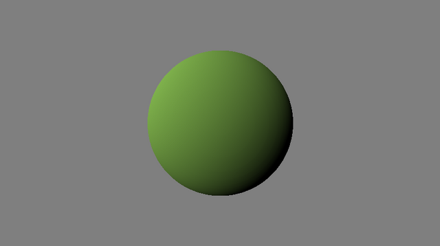
Now THAT is definitely a 3D sphere, not a 2D circle!
Next episode, we'll make our lighting model a bit fancier, before moving on to more complex scene geometry.
Shader gallery
The cool things we've made so far in the series.
Episode 8: Diffuse lighting
Episode 7: First raymarcher
Episode 5: Rotozoomer
Episode 4: Plasma
Thank you for contributing to #LearnWithSteem theme. This post has been upvoted by @daytona475 using @steemcurator09 account. We encourage you to keep publishing quality and original content in the Steemit ecosystem to earn support for your content.
Regards,
Team #Sevengers
The #learnwithsteem tag focuses on teaching through tutorials and lessons some knowledge, skill or profession that you have. Please avoid using it if it's not about that. Thank you!