Shader Programming: Massively parallel art [Episode 6: Camera]
Now that we've got used to the basics of GLSL shader programming, it's time to take it to the next level. Let's write a realtime raytracer!
I hope you'll forgive me for an episode that doesn't involve any pretty output at the end, but we have a little theoretical ground to cover first.
PART 6: Into the Third Dimension
As you know, we're abusing the concept of shaders a little here. While they are really meant to render materials within a 3D scene, our scene consists merely of a flat fullscreen quad.
If we want to render full 3D scenes, we would usually generate or load polygon geometry and push this to the GPU, while telling the GPU which polygons have which materials, and which shader programs should be run for each material in the scene.
That's how games, movies, and 99.9% of graphics programming is done today, but it does limit us to whatever capabilities are provided by the 3D polygon rendering pipeline implemented by the graphics card and exposed to us by OpenGL (or DirectX).
For example, although realtime raytracing capabilities are present in the latest generations of GPUs, if we wanted to write a realtime raytracer which would work on older GPUs, we'd be right out of luck trying to do it with the conventional rendering pipeline.
However, there is absolutely nothing to stop us implementing an entire 3D engine, including a scene and camera system, right inside our single fullscreen quad shader.
This completely frees us from all limitations imposed by the polygon pipeline, and allows us to use rendering techniques that our GPU has no formal support for. In fact, we are free to invent completely new rendering methods!
Over the next few episodes, we will build our very own GPU-based realtime raytracer.
While this sounds like a daunting prospect, you may end up amazed how little code we actually need to get it working.
So, raytracing: What is it?
You could argue that raytracing was invented in the 16th century by Albrecht Dürer, who popularised a method of making pictures with a "drawing frame".
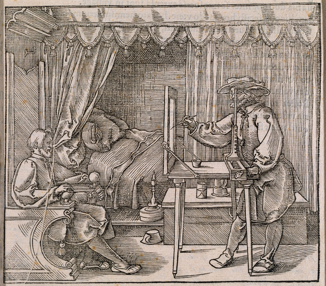
The artist on the right hand side views his subject through a thin sheet of paper divided into a grid, and draws in each grid square whatever he can see there. He's really tracing the subject.
We can imagine that his sheet of paper is our 2D screen, and that the subject behind is a 3D scene that we want to render.
For each grid square (pixel), we must trace a ray from the eye position, through the grid, and into the scene.
We can then check if that ray intersects with any object in our scene. If it does, we can colour the pixel in with the object's colour. If there's no intersection, we can just colour that pixel with a background color.
So, to sum up: We need to shoot a ray from the camera through every pixel of the image plane, and see if that ray hits something.
Here's an image which makes what we're trying to do a bit clearer.
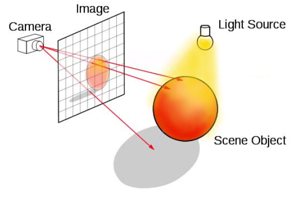
I'm with you so far! But what's a ray?
In the image above, every pixel in the image plane has a separate ray passing through it to check for object collisions, but only 3 are shown for example.
To specify a ray, we need a starting position in 3D space (in this case it's our eye / camera position), and a 3D direction vector. In GLSL, we can encode these using a pair of vec3s.
The eye position is easy enough, as it won't vary from pixel to pixel across the frame; but how can we figure out the ray direction?
This is another of those things that sounds more complicated than it is!
There are loads of different ways to calculate ray direction, using trigonometry, matrices, quaternions... the list goes on! However, if we make the small sacrifice of having a camera which is fixed in one position, we can make a massive simplification: We can directly use our pixel's uv coordinate to map the image plane into world space.
We'll treat our u coordinate (which varies horizontally across the image) as the worldspace x coordinate, and our v coodinate as worldspace y. I've made a diagram to show the relationship between these axes:
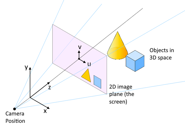
You can see that the coordinate system ends up such that the xz plane of the 3D space is the floor plane, with z increasing as we move further into the scene from the camera, and y increasing with height off the floor.
This is a popular conventional layout of axes in 3D graphics in general, and is known as the "left hand cartesian" coordinate system.
Note from the diagram above that the z axis passes through both the eye position and the center of the screen. Previously, our uv coordinates have been in the range {0..1}. For our current purpose, we need them in range {-1..1}, so that the {0,0} origin point is at the screen center, not at a corner.
That's easy; we just subtract 0.5 from each component and multiply by 2.
Finally, because our screen is rectangular not square, we multiply u by the aspect ratio so that our eventual image won't be distorted.
Head over to Shadertoy and paste the following in a new shader.
void mainImage(out vec4 fragColor, in vec2 fragCoord)
{
    // Calculate uv in range {-1..1}
    vec2 uv = (fragCoord / iResolution.xy - .5) * 2.;

    // Correct for aspect ratio
    uv.x *= iResolution.x / iResolution.y;

    // Define a camera position
    vec3 camPos = vec3(0, 0, -1);

    // Calculate ray direction for current pixel
    vec3 rayDir = vec3(uv, 1.);
    rayDir = normalize(rayDir);
}
(Don't expect it to render anything!)
Notice in the code that the rayDir vector simply takes uv as its xy components, and sets a constant value of 1.0 for the z component.
The value of this constant gives us an easy way to tweak the field of view of the camera; the higher the value, the narrower the field of view.
You'll also notice that we call the in-built GLSL normalize() function, as a direction vector should be normalized (that is, scaled so that the magnitude of the vector is 1.0).
We've set the camera position to be a little behind the origin at {0, 0, -1}, and we're "looking down" positive z.
OK... We've got our ray constructed (represented by camPos and rayDir), so the next thing we need is the ability to figure out whether or not that ray hits something in our scene.
Next episode, we'll add exactly that :)
Shader gallery
The cool things we've made so far in the series.
Thank you for contributing to #LearnWithSteem theme. This post has been upvoted by @fabio2614 using @steemcurator09 account. We encourage you to keep publishing quality and original content in the Steemit ecosystem to earn support for your content.
Regards,
Team #Sevengers