Learnwithsteem : Teaching robotics using the ESP32 board - Fourth lesson

Hi Steemians,
Often we find around us several so-called passive infrared sensors (PIR) which are generally used for security reasons or also for the operation of any automatically activated lighting system. In this fourth tutorial, we will show you how the HC-SR501 PIR motion sensor works and how you can use it with the ESP32 board.
How does the PIR sensor work?
These sensors do not emit anything (hence the passive in the name), but on the contrary capture the infrared radiation emitted by warm-blooded living beings passing through the detection field of the sensor. To widen the detection area, these are often covered with a so-called Fresnel lens. Various electronic components process the raw output of the sensor itself and provide a digital output based on detected motion.
You can also view this video to more understand how it works :
HC-SR501 motion sensor :
The HC-SR501 sensor has 3 pins as shown in the following figure :

| HC-SR50 Pins | To connect to |
|---|---|
| VCC | ESP32 5V |
| OUTPUT | Any ESP32's input Pin |
| GND | ESP32 GND Pin 0V |
This infrared sensor can be configured by its user. For this, it has two potentiometers to adjust the detection distance and the duration of the high state. There is also the possibility of configuring it in two operating modes thanks to a jumper to be placed between two pins.
Components Required :
To complete the assembly, you will need the following parts:
- LED
- Connecting wires
- Breadboard
- ESP32 development board
- PIR motion sensor (HC-SR501)

How to perform the assembly on the breadboard?
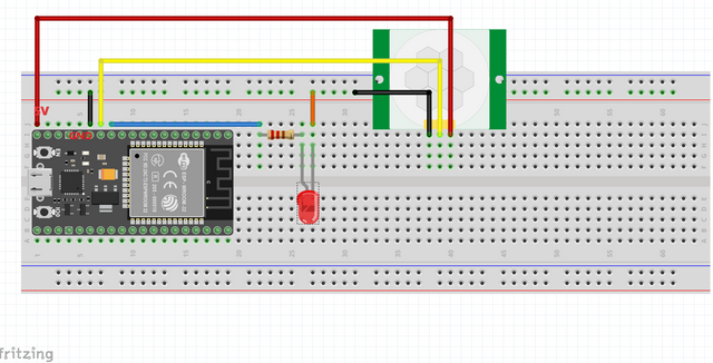
To carry out the assembly, we connect:
- The 5V power supply (or 3.3V depending on the model of the sensor) of the ESP32 card goes to the VCC pin of the sensor.
- The GND pin of the ESP32 board goes to the GND pin of the sensor.
- Pin D13 of the ESP32 board goes to the Output pin of the
sensor. - The D14 pin of the ESP32 board goes to the anode (+) pin of the
led diode and resistor.
Note: You can use all GPIOs as interrupts, except GPIO6 to GPIO11.
You can always consult the ESP32 pinout reference guide to know the location of each pin, for that I always provide you with this guide:


Coding :
Start by launching the Thonny editor and Open a new file and then copy the following code :
    from machine import Pin
    from time import sleep

    motion = False

    def handle_interrupt(pin):
          global motion
          motion = True
          global interrupt_pin
          interrupt_pin = pin

     led = Pin(12, Pin.OUT)
     pir = Pin(14, Pin.IN)

     pir.irq(trigger=Pin.IRQ_RISING, handler=handle_interrupt)

     while True:
           if motion:
                   print('Motion detected! Interrupt caused by:', interrupt_pin)
                   led.value(1)
                   sleep(10)
                   led.value(0)
                   print('Motion stopped!')
                   motion = False
To define the pins we always import the class of the module machine, also to define method timeouts we import the module time.
    from machine import Pin
    from time import sleep
Initialize a global variable named motion to False which will indicate the absence of detected motion.
motion = False
Then introduce the function handle_interrupt. which is called at each detected movement in which the variable motion will take the value True.
    def handle_interrupt(pin):
          global motion
          motion = True
          global interrupt_pin
          interrupt_pin = pin
Create two Pin objects, one for the LED on GPIO 12, and another for the PIR motion sensor on GPIO 14.
       led = Pin(12, Pin.OUT)
       pir = Pin(14, Pin.IN)
Set an interrupt on the pir by calling the irq() method.
pir.irq(trigger=Pin.IRQ_RISING, handler=handle_interrupt)
Every time motion is detected, we light up an LED for 10 seconds.
     while True:
           if motion:
                   print('Motion detected! Interrupt caused by:', interrupt_pin)
                   led.value(1)
                   sleep(10)
                   led.value(0)
                   print('Motion stopped!')
                   motion = False
The realization of assembly and the execution in image:
- Prepare all the necessary equipment:

- Start by connecting the HC-SR501 sensor , led and resistor to the breadboard and then use the wires to link its pins with the pins of ESP32.

- The LED should light up for 10 seconds when motion is detected, and a message should be printed in the Shell.

- After 10 seconds, the LED turns off.

- You should see the following output on the shell :
Thank you for your follow and see you in the next part.


Thanks for sharing to us useful and informative post... Great article about robotic writen by the experts
Thank you for contributing to #LearnWithSteem theme. This post has been upvoted by @Reminiscence01 using @steemcurator09 account. We encourage you to keep publishing quality and original content in the Steemit ecosystem to earn support for your content.
Regards,
Team #Sevengers
Hello @kouba01 Can you please unmute me so that I can be able to participate in the contest, promise not to Plagiarized again
This is quite lovely, I'm a great fan of Arduino programming as well before I eventually moved to raspberry and orange pi, Arduino comes with ease, by the way, maybe I had like to share my experience as well in the coming days.
Thanks for sharing !!
Interesting to see this on the ESP32 board rather than the PICAXE examples I usually come across
Hello, @kouba01. Your article has been supported using the @steemcurator05 account.
The language was very technical, I'll have to come back again later to give it another try, hehe.
Btw, are these sensors the ones used in automatic doors?
Nice tutorial! I like how you broke down everything to a layman understanding!
I'm Into Programming too. I'm a python teacher at steem skillshare. I make efficient use of the python modules and libraries in web development. I will also need your collaboration on GitHub as a fellow developer. And I have a project at hand titled "Student information system". Thanks for your cooperation in advance!
Regards,
@anyiglobal
@anyiglobalm Thank you for your comment. I am happy to find a colleague here, I have the honor to contribute to your projects. You can contact me through Discord: kouba01#2216
Ok thanks for the acceptance!
@kouba01 sir please unmute me from Crypto academy please sir