What is Logic Gate or Digital circuit (with truth table and diagram ) in physics and information technology?
Logic Gate-What is Logic Gate?
Digital electronics-What is Digital electronics?
A signal having only two levels of information is called digital signal, The two levels are "yes" corresponding to (one) and "no" corresponding to (zero) 0.
Thus the digital circuit makes use of the only two digits zero (0) and one (1) of binary number system.
Circuit handling such signals are called digital circuit. Clearly in any digital circuit only two values represented by 0 and 1 of the input and output voltage are permissible.
When 0 and 1 represent the low and high value of the uot voltage respectively, the system is called a positive logic system .
On the other hand ,if 0 and 1 are represented the high and low values of voltage respectively, then this is called a negative logic system.
In most digital circuit diode and the transistors are used as a switches,Which is changed from one voltage levle to another since a switchis may be open or close.
The two input states of digital circuit may also be assigned "off" and "on" states. In positive logic system the two states 0 and 1 respectively.
Logic Gate or Logic Circuits-
Any digital circuits that can be analyzed with the help of Boolean Algebra is known as logic Gate or logic circuits.
It can also be defined as the logic circuit which may either allow a signal pass though or stop.
The mos important commanly employed logic gates are OR,NOT,AND. These are some compound gates such as NOR and NAND gate.
* There are different Logic gates or circuits-
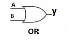
1) OR GATE-
In OR gate has two or more input but only one output.In the symbolic representation above the picture A and B are input and with respect to output is Y.
(A+B=Y) .
It is read as A or B equals to Y. It is realized by using two diodes and a load resistance as shown in the circuit.
The Truth Table of OR GATE-
  A        B              A+B=Y

  0           0                    0

  0           1                    1

   1           0                    1

   1           1                     1
Clearly a truth table indicates that the output of a logic for the given inputs.
2) AND GATE-
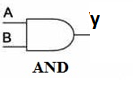
In AND Gate has two or more input but only one output. This gate is also known as coincidence circuit. In the represented above A and B are input and Y is the output.
It follows the Boolean Expression A.B=Y, which can be read A and B equals to Y. It can be realized again by using diode but in different manner.
The Truth Table of AND GATE-
 A        B         A.B=Y

   0        0            0

   0        1            0

   1        0            0

   1        1             1
3) NOT GATE-
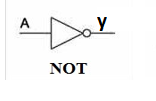
NOT gate has only one input and oputput is also one.In above Symbol A is input and y is output.A NOT gate is also called an circuit. The Boolean Expression for NOT Gate is A'=Y
The Truth Table of NOT GATE-
A       Y'

0        1

1        0
4) NOR GATE-
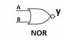
THE Truth Table-
A        B         A.B=Y       Y'

0        0           0             1

0        1            0             0

1        0            0             0

1        1             1             0
5) NAND GATE-
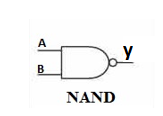
It is also the combination form of NOT and AND gate . It follows the Boollean expression , that is -AB'=Y
It can be read as A and B negated equals to Y.
The Truth Table-
  A        B         A.B=Y       AB'=Y

   0        0            0               1

   0        1            0               1

   1        0            0               1

    1        1             1               0
"I am Very happy to help something"
"THANKS GUYS "