S19-Wk5: Rectifier circuit design
Captured and edited With Galaxy-A15
Rectifier Circuit Design
Terminologies
Rectrifier
A circuit that accepts Alternating current as its input and gives out Direct current as its output.
Transformer
An electronic component that induces a cirrent flowing in one coil due to the current flowing in another coil that are not physically connected.
Diode
An electronic device that allows electric current to flow across it in only one direction.
Alternating current (AC)
This type of current only had a magnitude but no fixed directio. As it continously switches polarity. Its easy to generate and transmit.
Direct current (DC)
This is a type of electric curent that has both a magnitude and a direction. Its easy to save in cells and used by most electronics.
Working principal of the rectrifier
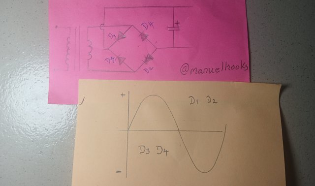
When the AC form wave is in its positive phase, D1 and D2 becoms forward biased, resulting in current flowing through them. At that time, D3 and D4 are not idle.
But during the negative phase of the wave, it makes D3 and D4 forward biased and atvthat point they are conducting but D1 and D2 are waiting for the next positive phase.
Assignment [Task 1]
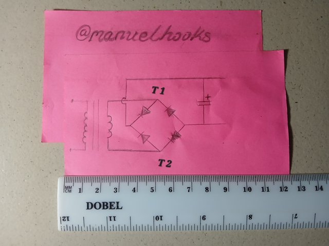
Full wave rectifier circuit
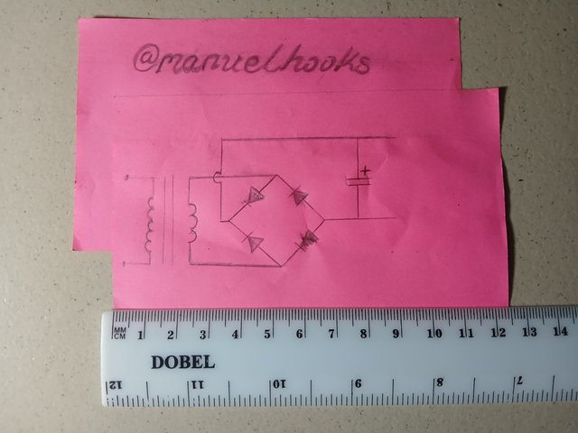
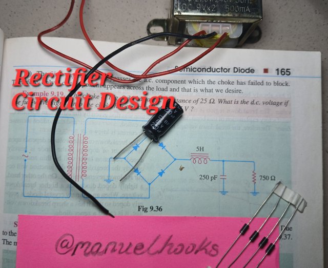
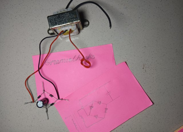
Starting with a circuit diagram that will serve as a guide.
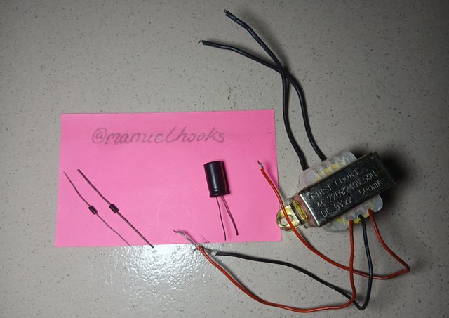
Collecting all the needed components for the rectrifier
| Quantity | Component | Description |
|---|---|---|
| 1 | Transformer | 220 to 9v |
| 4 | Diodes | 1N4001 |
| 1 | Capacitor | 63V 220μf |
Construction Process
[Step 1]
Get two diodes and connect them anode to anode while another two are connected cathode to cathode as shown in this picture.
[Step 2]
Now i connected the two sets of diodes together
[Step 3]
Its time to add a capacitor to the rectrifier
[Step 4]
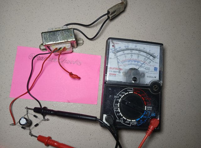
Add a transformer to the rectrifier
Testing
Transformer output
Testing the AC output of the step down transformar at the secondary.
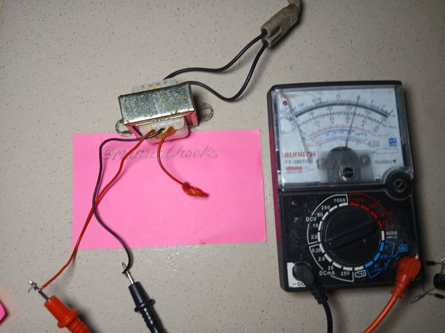
Observation:
| Having my analogue meter set to AC and the range being adjusted to 10, the reading i got was the meter is 6.5V of AC |
|---|
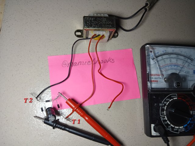
Transformer output with load
Testing the steped down AC voltage supplied by the transformer when the rectrifier is connected
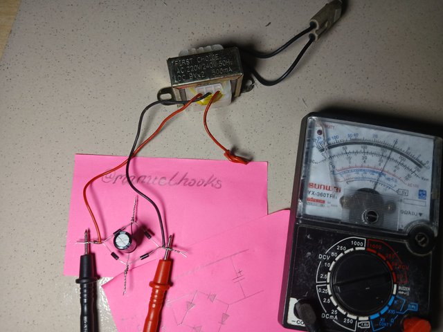
Observation:
| With the meter set to AC and the range being 10, the reading on the meter is 6.5V of AC, no observable voltage drop with the introduction of the rectrifier as a load |
|---|
Rectrifier output without Capacitor
To observe the capacitors contribution, i tested the rectrifier's output voltage without the electrolitic capacitor
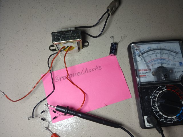
Observation:
| With the meter set to DC and the range being 10, the reading we have on the meter is 5.5V of DC |
|---|
Rectrifier output with Capacitor
Testing the DC voltage supplied by the complete full wave rectrifier with capacitor while maintaining every other paramiters.
Observation:
| With the meter set to DC and the range being 10, the reading I have on the meter is 8.5V of DC. A difference of 3 Voltes is observed with the capacitor in place |
|---|
Assignment [Task 2]
Functions of a Rectrifier
Besides using a rectrifier to Convert AC power to DC power DC, funcrion as a battery charger (Mobile Charger, Laptop Charger etc) and Powers DC lights and fans
Use in AM Radio
A rectrifier is used in Amplitude Modulation Radios to separate the intelligent massage from the carrier waves thereby extracting the audio signals from the waves.
Clock generation
Rectrifiers are used to create DC voltage that comes in the form of pulses that can be used as a clock signal generator for digital electronics. This will mean converting AC to DC without smoothening the output with a capacitor.
Timing circuit
Rectrifiers are to produce input signals for a timing circuit.
Soft clipping
Rectrifiers are used to createa kind of soft clipping effect in some amplifiers systems
Assignment [Task 3]
Observations and precautions
Observations
The transformers connection between points T1 and T2 can be interchanged without any effect on the circuit.
The red and black cable can be interchanged without any problem.
It was also observed that the capacitor playes an important role in boosting the output power with about 3 voltes
Precautions
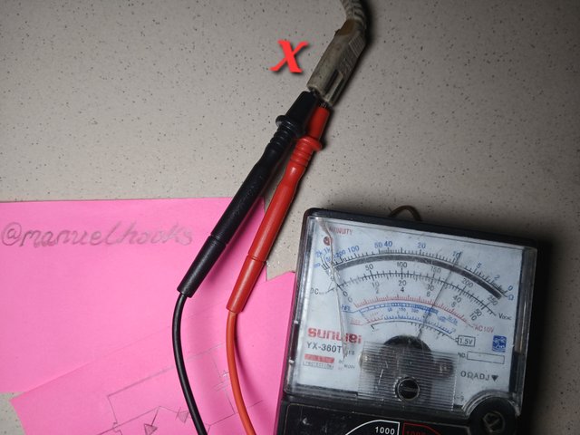
The voltage at the point marked x is high enough to deliver a deadly shock as it carries 170 voltes of alternating current.
When testing this point, be sure your metter is correctly set to avoid loosing it to high voltage.
I had to be careful not to reverse the connection of the electrolitic capacitor, as such could result in a loud bang.
I was careful not to mix the orientation of the diodes
I had to be careful, because i was measuring both AC and DC so would have to switch functions accordingly. And i also had high voltage to work with.
Conclusion:
I did not know that rectrifiers could be used in so many situations.
At the end i was able to successfully run a 12 voltes DC mottor on a rectrifier and transformar that cutdown and transform 170V AC to 8.5V DC, safe enough to use on small electronics components like a DC mottor.
Invitation to contest
I am inviting @bossj23, @jozzie90, @josepha and @oasiskp
#electronicss19w5 #steemexclusive #nigeria #burnsteem25 #learnwithsteem
#electronics #club5050
Upvoted. Thank You for sending some of your rewards to @null. It will make Steem stronger.
Was looking forward to your assignment. As expected it's really detailed. Wishing you the best sir.