S19-Wk5: Rectifier circuit design
Good day Everyone.
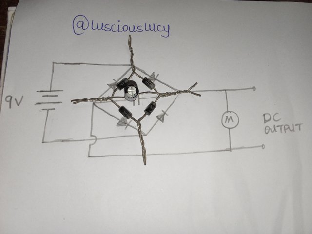
A rectifier circuit is an electrical circuit that converts alternating current (AC) to direct current (DC).
The rectifier circuit consists of:
Diodes: These allow current to flow in one direction, blocking the reverse flow. Four bridge diodes in this design. Opposite sides shares the same positioning of the anode + and cathode -.
AC input: Transformer; steps down or steps up the AC voltage. Or substituting the transformer with a 9 volt Battery.
Filtering components: Capacitor.
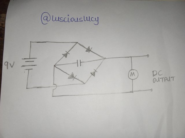
Task 1: Build a full wave rectifier circuit like the one we have above, outline the steps you took to build. Measure and indicate the DC output.
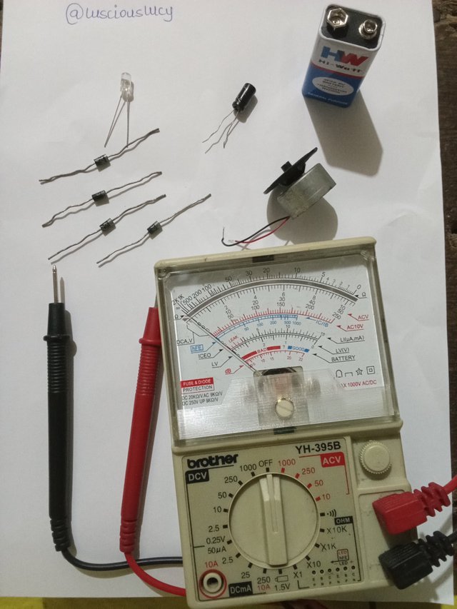
Components used:
- 4 pieces of IN5399 rectifier diode
- 1 piece of 100μf capacitor
- Motor (substitute fan)
- 1 piece of 9 volt Hi-Watt battery
- Jumper wire
- Meter
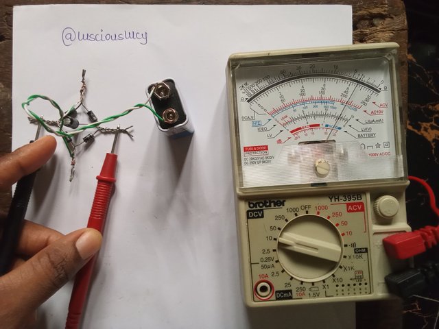
STEP 1
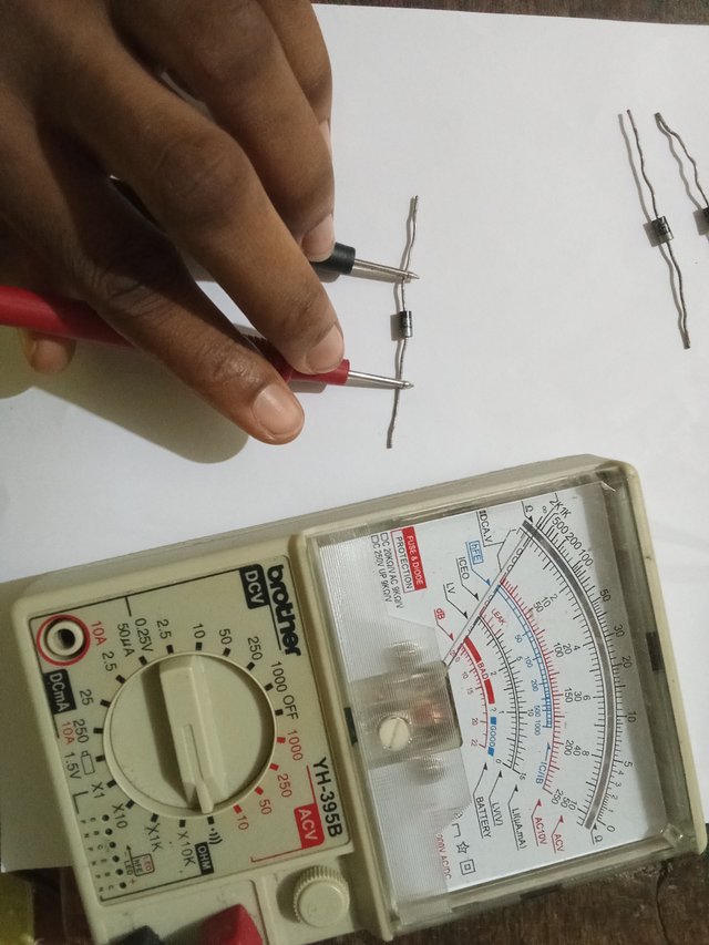
Testing the polarity of the rectifier by switching the meter nob to continuity. It beeps continuously when the probe is placed properly as in the picture.
STEP 2
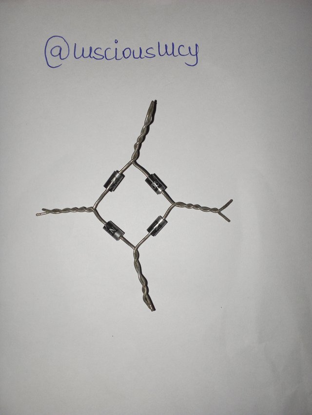
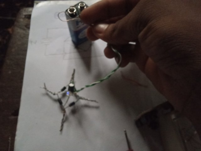
Joining the four rectifier diodes together.
STEP 3
Connecting the capacitor.
STEP 4
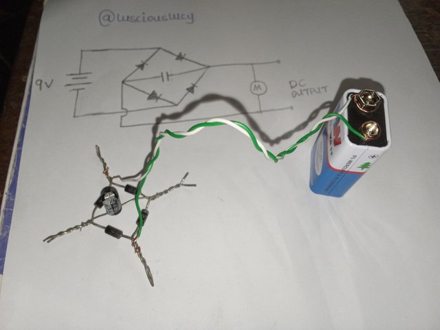
Connecting the battery
STEP 5
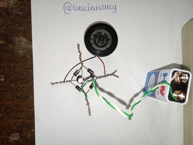
Connecting the motor. The motor start whirling.
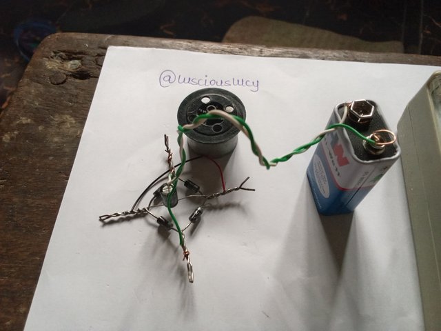
Disconnected the battery and it stopped whirling
STEPS
Drawing and understanding the circuit diagram.
Identifying the needed components.
Testing to know the polarity of my diode.
Identifying the negative and positive terminal of the capacitor.
Joining the diodes; 2 positive to positive, and the other 2 negative to negative before joining the sides to get the diamond shape.
Placing the capacitor: positive to positive and negative to negative.
Connecting the electric motor same way as capacitor.
Connecting my battery to the circuit.
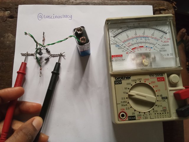
Since I'm using a 9 volt battery, I kept the meter switch on 10v in DCV.
Took the positive probe to the positive leg of the circuit and negative to negative and took the reading.
Measuring the DC output:
Switch the meter nob to 10volt on DCV which is slightly above the battery range of 9 volt.
Place the probe on the corresponding polarity.
It measured 8.30 volt.
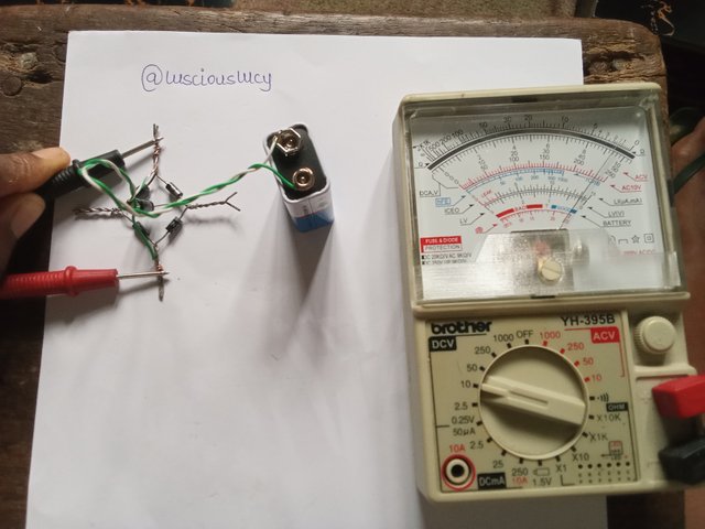
At some point the reading fluctuated but more repeatedly, I got the a value close to that of the battery.
Switched the probe for confirmation
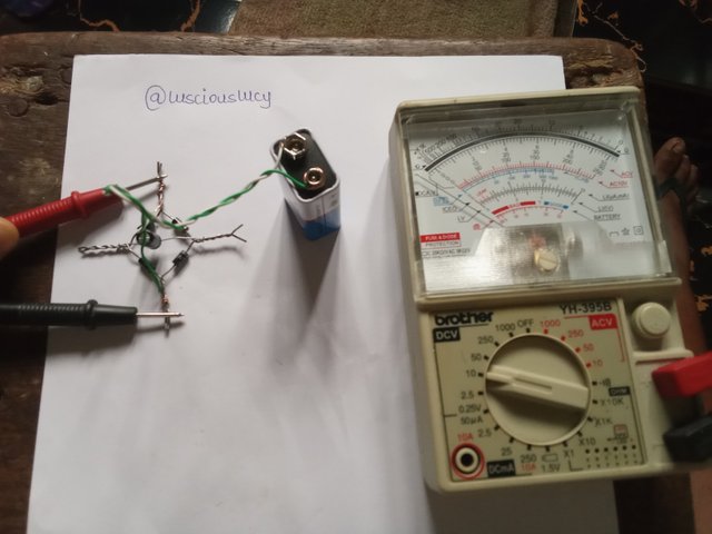
Measure the AC input
Task 2: Discuss 5 additional applications of the rectifier circuit, apart from the ones we previously mentioned.
Power Supplies: Convert AC to DC for electronic devices like; television, computers and smartphones.
Motor Control: Convert AC to DC for motor windings control in industrial applications such as; speed control, direction control etc
Telecommunications: Rectifier circuits are used in telecommunications equipment, such as phone exchanges, routers and servers, to convert AC power to DC power.
Industrial Control Systems: Rectifier circuits are used in industrial control systems for manufacturing, automation and power control, such as programmable logic controllers to convert AC power to DC power for the control circuitry.
Audio Equipment: Power amplifiers and speakers in audio systems.
Task 3: What were your observations while building the full wave rectifier circuit, and what precautions did you take?
Observations:
- If the components are not properly fixed, this could cause wrong readings.
- The energy source is connected in a way that it transmits energy all through the diodes to the load.
*Point of connection does not really matter for the battery but the capacitor should be connected to the right points. - The capacitor retains energy and also collect the energy from the battery.
Test to prove: Using LED
Connecting LED directly to battery blows up the led but in this case, the light was bright, and when disconnected from the battery, the light went dim before being off completely.
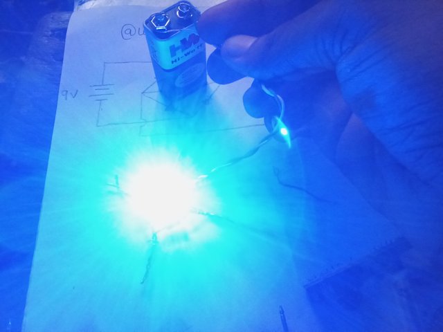
Emphasis on proper connection. The first LED blew up because I connected on the AC.
Precautions:
- Checked if the meter is in good shape through continuity test.
- Ensured the diodes are tested and connected properly.
- And the capacitor fixed correctly.
- Firmly tighten the the battery connection
- Ensure tight connection.
Bridge rectifier passes energy all round it's connection and the rectifier circuit is used in many applications where conversion of AC power to DC power is required.
This week's practical was easy and enjoyable though getting the reading was a bit of an hassle. Building the circuit and getting the output was thrilling.
Thank you, friend!


I'm @steem.history, who is steem witness.
Thank you for witnessvoting for me.
please click it!
(Go to https://steemit.com/~witnesses and type fbslo at the bottom of the page)
The weight is reduced because of the lack of Voting Power. If you vote for me as a witness, you can get my little vote.
From your conclusion it shows that you are now enjoying this electronics training.
Your assignments are getting better every day. At 8.5 out of ten, hou are already flying. Keep it up and congratulations.
Yes I am.
Thank you sir.