Simple 5V Mobile Charger Circuit – Easy DIY USB Charging Solution.
Assalamualaikum Everyone. I am @imranhassan
From #Bangladesh
.png)
A mobile charger is an essential device that helps in charging smartphones and other USB-powered devices. In this post, I will discuss a simple 5V USB mobile charger circuit, its working principle, and the required components. This circuit is designed using a 7805 voltage regulator, which provides a stable 5V output suitable for charging mobile phones.
For this mobile charger circuit, the following components are required:. List of components:
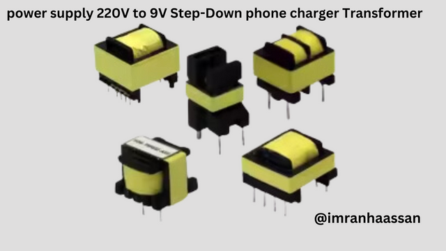
| 1- 220V to 9V step-down transformer: Converts high AC voltage to low AC voltage |
|---|
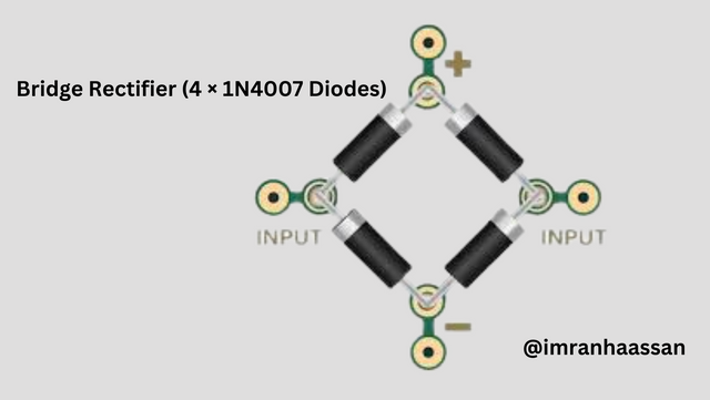
| 2- Bridge rectifier (4 × 1N4007 diodes): Converts AC voltage to DC |
|---|
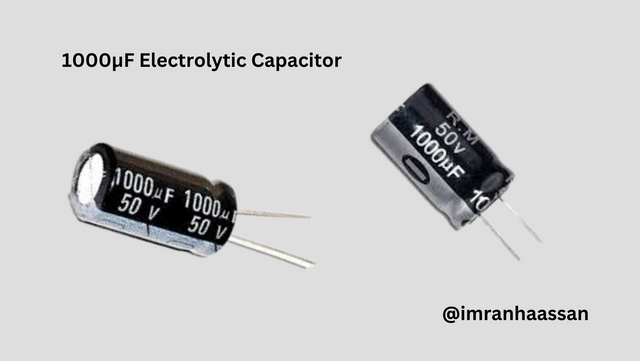
| 3- 1000µF Electrolytic Capacitor: Smoothes the DC voltage |
|---|
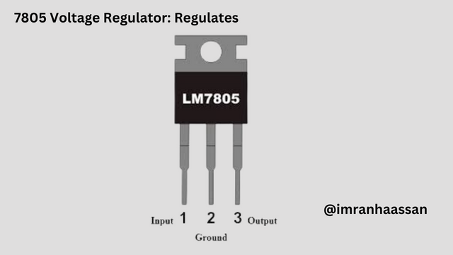
| 4- 7805 Voltage Regulator: Regulates the voltage to a stable 5V output |
|---|
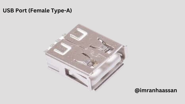
| 5- USB Port (Female Type-A): To connect the mobile phone charger cable |
|---|
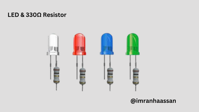
| 6- LED and 330Ω resistor—power indicator |
|---|
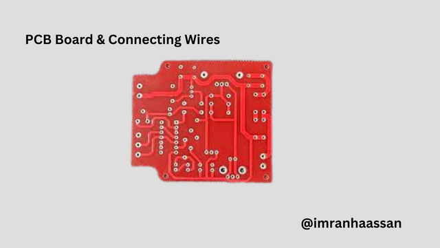
| 7- PCB board and connecting wires—to assemble the circuit |
|---|
| Working principle of a simple mobile charger circuit how do we get 5V DC from 220V AC? Now I will explain about a simple mobile charger circuit. I made it myself and drew its circuit diagram in a notebook, which you can easily understand. Let's see how it works step by step. |
|---|
| Step 1: Step down voltage |
|---|
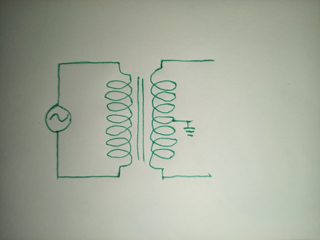
First of all, a 220V AC input cannot be used directly for a mobile charger because it is too high voltage. So, I drew and used a transformer that steps down from 220V AC to 9V AC.
| Step 2: AC to DC Conversion |
|---|
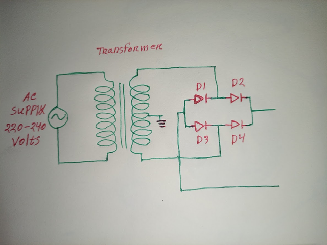
After getting 9V AC, it cannot be used directly for mobile charging because the mobile charging circuit works on DC voltage. For this, I have used a bridge rectifier (made of 4 diodes), which converts AC to DC. However, this DC voltage is still not completely smooth.
| Step 3: Smoothing the DC voltage |
|---|
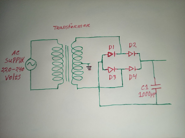
Since the output of the bridge rectifier is not smooth DC, I have used a 1000µF capacitor. It filters the voltage and removes the ripple (AC component) so that a stable DC is obtained.
| Step 4: Voltage Regulation |
|---|
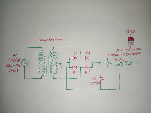
Now we have 9V DC, but we need 5V DC for mobile charging. So I have used a 7805 voltage regulator, which converts 9V to 5V DC and ensures a stable voltage output.
| Step 5: LED Indicator (LED Indicator for Power Status) |
|---|
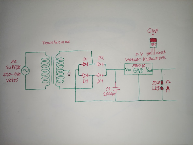
Finally, I used an LED and a 330Ω resistor, which lights up when the circuit is turned on. This will act as an indicator for the user and show whether the charger is working properly or not.
| Step 6: USB Output (Power Output via USB) |
|---|
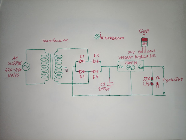
After getting 5V DC from the regulator, I connected it to a USB port. As a result, a mobile or any other USB-powered device can be safely charged through this circuit.
| Final Thoughts |
|---|
This circuit is a basic mobile charger circuit, which converts AC to DC, filters, regulates, and outputs a safe 5V. This is a great project for learning electronics! I have drawn a circuit diagram of it in a notebook, which you can easily practice by looking at it.
.gif)
A great post. Explained the 5V mobile charger circuit in simple language in detail which anyone can easily understand. The step-by-step circuit making method is amazing. Especially the explanation of getting 5V stable output using 7805 voltage regulator is very clear. Thanks for such an informative post.