SLC-S22/W5 || Ladder Diagram PLC Programming and Solar Power.
Assalam-o-Alaikum! |
|---|
Hello friends! I'm @moazzamushtaq from #pakistan and I warmly welcome all of you to my post. I hope that you all will be fine and will be enjoying your lives. Today I'm going to participate in the SLC-S22/W5. The topic is "Ladder Diagram PLC Programming and Solar Power" and teacher of this course is @mahadisalim. Let's start the topic;
What is meant by ladder diagram PLC programming? Draw a ladder diagram and explain. |
|---|
Ladder diagram is a programming language represents graphically and is used to program programable logic controller (PLCs). Ladder Diagram is widely used and is popular graphical method used for PLCs. This ladder diagram resembles with electrical ladder diagram and have to vertical rails and rungs. Rails represent power supply and rungs shows to control system.
Here are the breakdown of basic components mention in the image:
Rungs: These are horizental lines that represents the control logic.
Contacts: They represent the input to the PLC such as switches or sensors.
Coils: Coils represent the output to the PLC such as valves or actuators.
Functions: They show the more complex logic operations such as timers, counters or arethmic operations.
Write the work by drawing the symbols of the input and output elements of the ladder diagram. |
|---|
In Ladder diagram, the input and output symbols have specific role. Below are the drawings of both input and put elements.
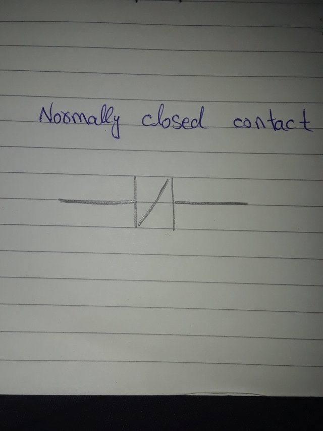
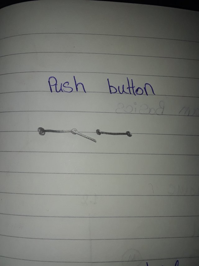
Input symbols:
Input symbels are typically used to enter the data into programable logic controller. Some input symbols are
- Normally open contact:
Normally open contect is closed when the input signal is activated which shows that now circuit is complete.

- Normally closed contact:
The contact opens when output signal is activated. Normally it remain closed but open when signal activated showing the cricuit is disconnected.
- Push button:
Push button is responsible either the current flow in the curcuit or not. Mean when this button is closed, the current is flowing and if open, the circuit is disconnected.
Output elements
Output elements are those which represent the output flow of current or signals in the circuit. There are several output elements that are used in Ladder diagram, e.g coil.
Coil:
Typically a coil is a series of loops, rings or spirals. But in ladder diagram it is a output element and have a role in flowing the current or signal in the circuit.

Draw the ladder diagram with three input ladder logic gates (AND, OR) and explain with practicals.[With symbols and truth tables] |
|---|
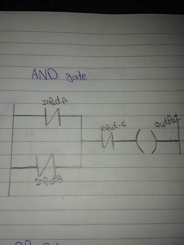
AND Gate:
And gate is logic gate which have multiple inputs but has only one output. When all inputs are equal to 1, mean the circuit is activated.
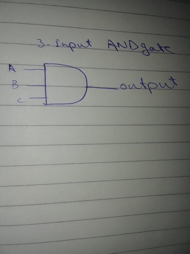
In below diagram there are 3 inputs in the circuit and giving only 1 output which shows the circuit is completed.
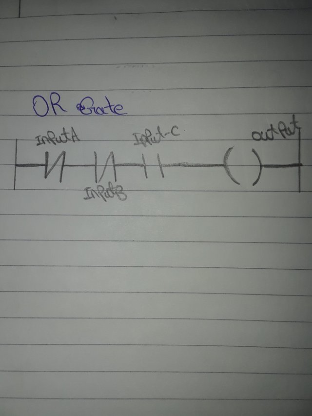
OR Gate:
OR gate is a digital logic gate which have output 1, only when one of its input is 1 or output will be 0.
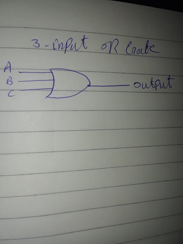
3 Input OR gate
Truth Table
● Formulas
- OR gate: A+B+C (output)
- AND gate: A.B.C (output)
Below is the truth table for three inputs of both OR gate and AND gate.
| Input A | Input B | Input C | AND output | OR output |
|---|---|---|---|---|
| 0 | 0 | 0 | 0 | 0 |
| 0 | 0 | 1 | 0 | 1 |
| 0 | 1 | 0 | 0 | 1 |
| 0 | 1 | 1 | 0 | 1 |
| 1 | 0 | 0 | 0 | 1 |
| 1 | 0 | 1 | 0 | 1 |
| 1 | 1 | 0 | 0 | 1 |
| 1 | 1 | 1 | 1 | 1 |
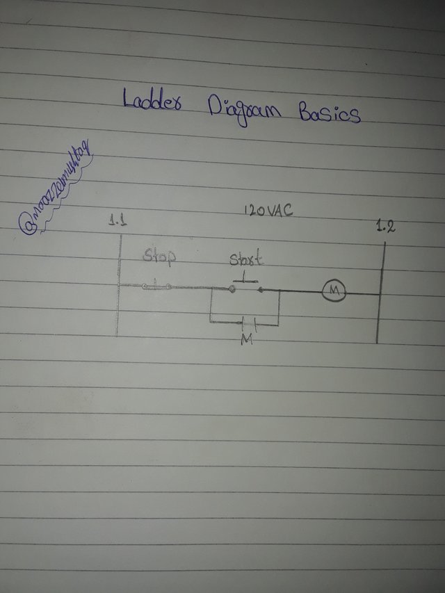
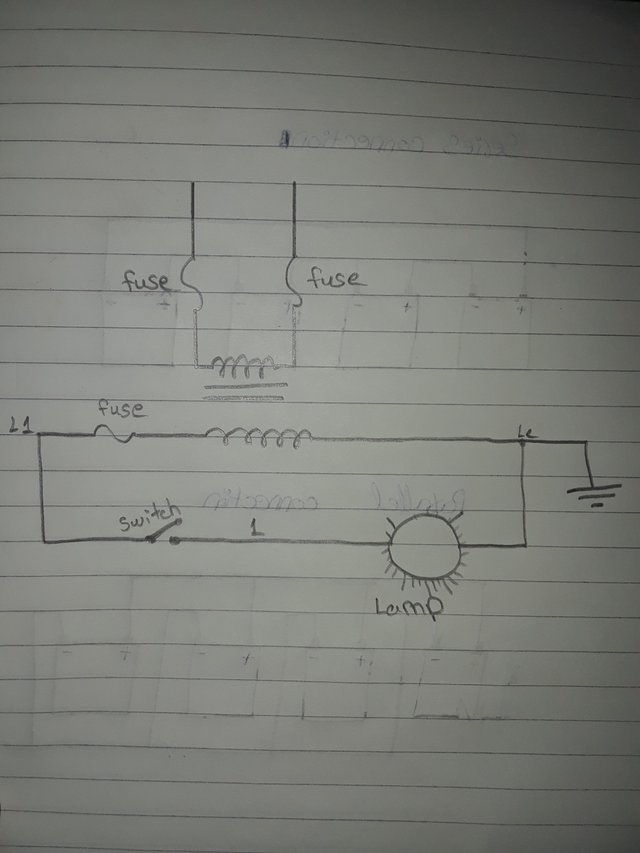
Convert the electrical wiring in the figure below into a ladder diagram. |
|---|
Eectrical wiring of the figure can be converted easily by following some key points.
● For power supply a vertical line is drawn in left side and for neutral supply a vertical line is drawn on right side.
● Starting from the left rail a push button as closed contact NC is added.
● Next buttons
- ON push button
- Start push button as NO
● Than add coil in the diagram.
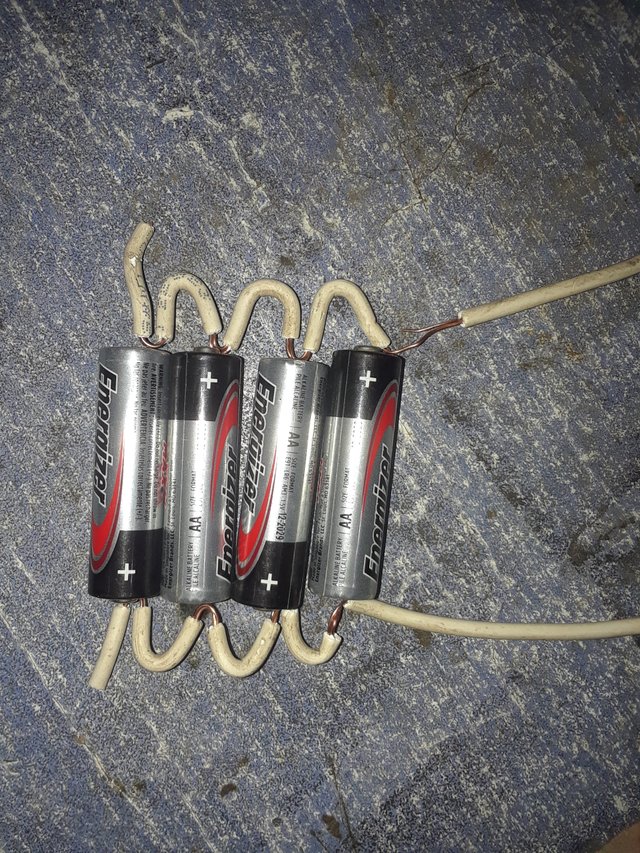
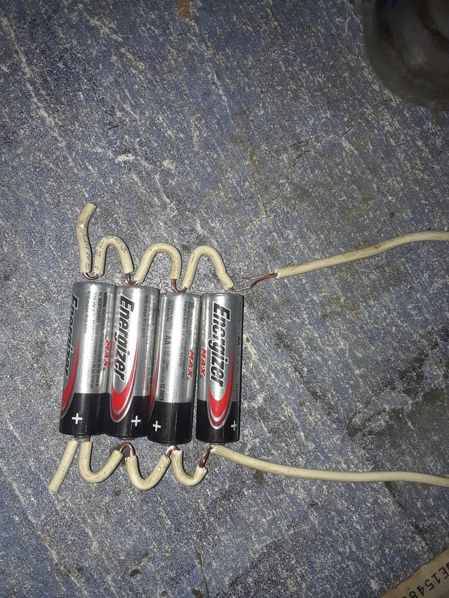
Solar power is generated in your home with three 12-volt 100 AH batteries. An additional 12-volt 100 AH battery needs to be connected as your home's electrical load increases. Explain the series and parallel connection of four batteries with diagrams. [Note: Practical can be done with multiple batteries of any rating.] |
|---|
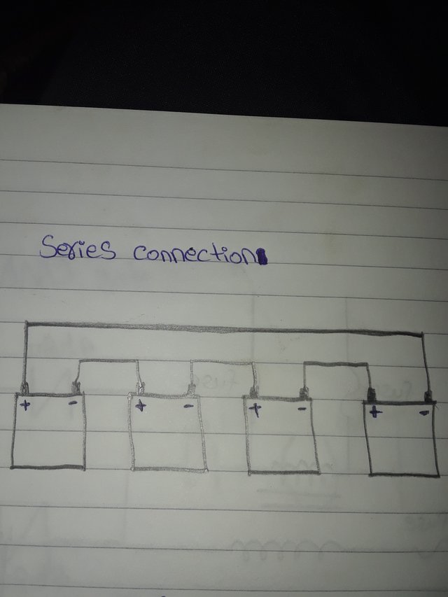
Series Connection:
In series connection the voltages are changed but capacitance remain unchanged. So by adding voltages of 4 battries
4 battries= 12+12+12+12
= 48 volts
Capacity= 100 AH
Connection method:
In series connection positive terminal of one battery is connected to negative terminal of second battery and so on for all battries. Below is shown the connecting method.
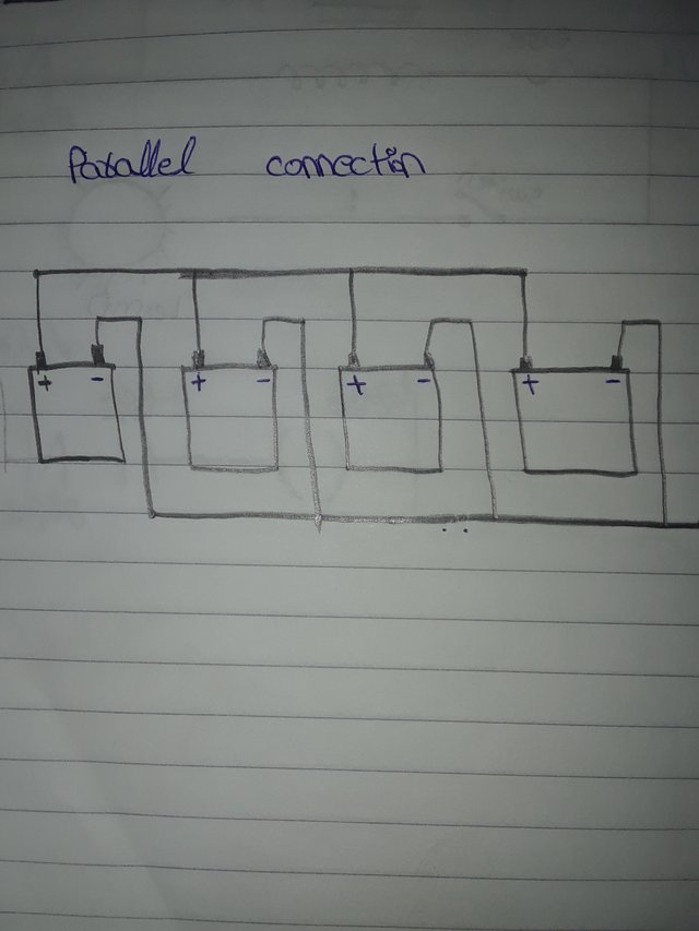
Parallel Connection:
In parallel connection voltages of battries remain same buy capacitance changes.
Voltages = 12 V
Capacitance of 4 battries = 100×4
= 400 AH
Connection method:
In case of parallel connection, the postive sides of all battries are connected to each other and negative connected to each other.
All pictures are captured by me using mobile samsung J3 prime. |
|---|
I invite @drcrypto1, @sahar78 and @josepha.
Thanks.
Author:
@moazzamushtaq.