How To Make Your Own Bank Power
How To Make Your Own Bank Power
How to Make Power Bank. Power bank is an electronic device in the form of battery that serves as a backup power storage for gadgets that we use. When we travel far for example, of course the power bank is needed when the gadget undergoes lowbatt so we do not need to find 220 AC power outlet to charge the gadget, just connect usb to the power bank then gadget will be filled like charging using electricity at home. That's why power banks are also referred to as portable chargers.
In this post will be explained about how to make your own power bank using simple components at an affordable price. By making our own power bank certainly do not need to buy power bank in the store, and certainly there will be satisfaction in itself because it has added insight about electronic devices, it is more important.
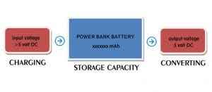
the basic system of making power bank
Basically the power bank system consists of 3 main parts namely:
Charging: battery charging process of bank power
Storage capacity: The storage capacity of the bank power battery with mAh unit
Converting: the process of adjusting the input voltage to the gadget, the average gadget like hp android requires input voltage for charging of 5 volts.
Tools and Components:
4 pcs rechargeable battery (as needed)
Cable usb charger
Avo meter
IC voltage regulator 7805
Capacitor elco 470uF
Capacitor 1uF
Diode 1N4001 / equivalent
Usb plug plug socket connector
Pcb.
Here's a picture of the tools and components for the power bank circuit:
.jpeg)
female usb socket.
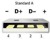.jpeg)
konfigurasi pin usb
.jpeg)
pinout voltage regulator 7805
For Battery series as below:
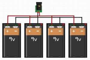.jpeg)
parallel circuit 4 9 volt battery
.jpeg)
the parallel circuit of 4 AA batteries
Keep the battery used is rechargeable batteries so that if the power runs out then can the contents (charging) back, in this post is not explained about the charging power bank (input), just described the output in the form of DC to DC converter connected to the gadget.
This post contains basic knowledge in making the power bank, for a more complete explanation of the power bank already in the form of ready-made pcb module will be discussed here (pending ....).
If the battery is paralleled then the voltage will remain but the current capacity that can be drawn by the load is greater.
If the battery is diseruished then the voltage will increase but the capacitance of the tensile current can be fixed. Read more below:
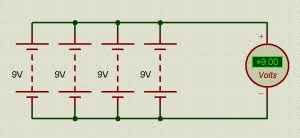.jpeg)
the voltage parallel circuit is fixed, the current increases
.jpeg)
voltage series circuit increases, fixed current
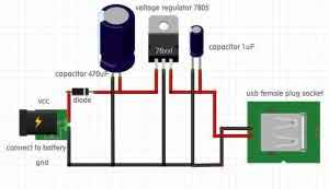
a series of power Bank simple as below:
.jpeg)
voltage conversion circuit for power bank
Explanation of the series as follows:
Connect the Vcc (+) section to the red wire
Connect the gnd (-) to the black wire
The diodes in the circuit function to avoid backflow so that the battery remains safe.
Actually without the capacitor is not a problem and the circuit still works, but to keep the ic regulator working properly if given the load then it should be installed capacitors. Capacitors also serve as a smoothing more here.
LM7805 is a ic regulator that serves to convert the incoming voltage to 5 volts, provided that the input voltage to 7805 should be greater than 5 volts. If it is below 5 volts then the output voltage LM7805 will go down as well. This is called a drop voltage.
At the output voltage of 7805 connect the capacitor elco 1uF / ceramic 1 uF, then connect (+) to pin vcc and (-) to pin gnd female usb plug socket consisting of 4 feet, usb usb configuration we can see the above picture .
May be useful.