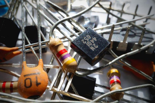
Introduction to Basic Electronic Components #3: Come Learn How to Build Basic Electronic Devices

Yesterday was fun I guess. We were able learn about resistors - how they look like, how to interpret their color code, how to calculate the Equivalent Circuit Resistance of a resistor in parallel or series connection. If you missed yesterday's post and that of the day before you can check them out using the links below
Introduction to Basic Electronic Components #1
Introduction to Basic Electronic Components #2
Well for today we will look at capacitors, but before we jump into capacitors, let's talk about polarity in electronic components
What is polarity?
I know that polarity is not a new phenomenon. Most of us already know about polarity but do we know how polarity affects our electronic circuit?
The polarity of an electronic component tells us how to connect that component in our circuit. If an electronic component is polarized, it means it has a positive and a negative terminal. We would need to connect the positive terminal to the positive part of our battery and the negative terminal to the negative part of our battery. If we were to connect it otherwise, we would end up frying that electronic component.
Not all electronic components are polarized, some are while some are not. I forgot to mention yesterday that resistors are not polarized, I did this purposely because I hadn't talked about polarity.
The Capacitors
What are capacitors?
Capacitors are electronic devices that have two plates separated by an Insulator (poor conductor). Any type of insulator would do. Common insulators used in capacitors include mica , glass, plastic film, paper etc.
What do they do?
Capacitors store charges. We can think of capacitors as very big tanks that store water when there is excess and supplies back the water stored when there is drought. When a capacitor is fully charged and is connected to a circuit, it behaves like a battery supplying current for a short period of time until it is discharged.

The effect of a capacitor in a circuit is known as its capacitance. The capacitance of a capacitor varies directly with the surface area of the the plates and inversely with the distance between the plate. That is, the larger the plates used in a capacitor the larger the capacitance and the larger the distance between the plates the smaller the capacitance of that capacitor.
The capacitance of a capacitor is measured in farads (F). The typical values of capacitors used in most electron circuits fall within the picofarads (pF), the microfarads(mF) and the millifarads (mF).
Types of Capacitors
Generally speaking, there are majorly two types of capacitors used in electronic devices. They are:
- The Ceramic Capacitors, and
- The Electrolytic Capacitors
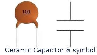
The ceramic capacitors look like small round flat drug tablets with leads pointing out of it. Ceramic capacitors are usually not polarized. This means that they can be connected in a circuit as one pleases, whichever leg of the capacitor to the positive terminal of the battery (Vcc) or to the negative terminal of the battery (Gnd). The image and symbol of a ceramic capacitor is shown below

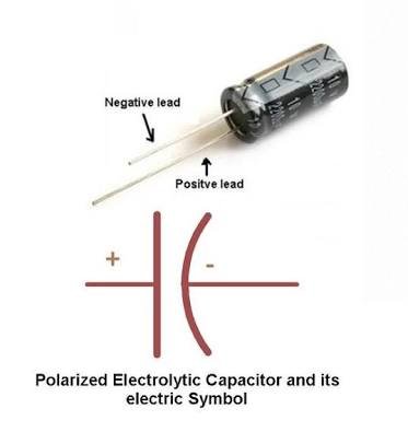
The electrolytic capacitors look like small cylindrical object with legs pointing out of it. Electrolytic capacitors are polarized, meaning that we have to be cautious on how we connect this type of capacitor to a circuit. The positive leg of the capacitor to the Vcc and the negative leg of the capacitor to the Gnd. The image and symbol of an electrolytic capacitor is shown below

How do they function?
As you may have noticed in both the images of a capacitor above and in my definition of a capacitor, the two plates making up a capacitor are separated by a non conductor.
Am sure your next question would be, How then does current flow through it?
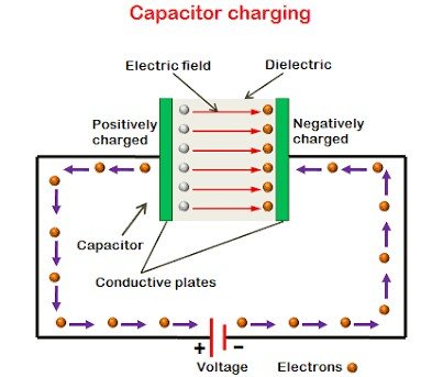
The real truth is that current doesn't flow through a capacitor. What it doesn't? Yes it doesn't. Then how does it perform its function? Well at first the two plates making up the capacitor are initially neutrally charged. But when a potential difference is placed across a capacitor it causes electrons to leave one plate and flow into the other plate through the battery and not through the insulator (remember, insulators don't conduct), causing a net positive charge at one plate and a net negative charge at the other plate making it seem as though current is flowing.

Charging of a Capacitor
As we've seen a potential difference across a capacitor results in a net positive charge on one plate and a net negative charge on the other plate. If this continues a point will reach where the capacitor is fully charged and the potential difference that has built up across the capacitor equals the potential of the battery.
This causes opposition to the flow of current, as no current will flow through the capacitor. Making the capacitors at this point to behave like a resistor - a Time Dependent Resistor (TDR) to be precise. This brings to light my statement in the previous post
As we will get to see in subsequent posts, virtually all basic electronic components tend to offer some form of opposition to current flow.
Not to worry, I won't go into detail on this. But in subsequent post we will get to see how this behavior of a capacitor can be put to great use in the design of electronic circuits.
Capacitor Configuration
Capacitors just as resistors can be connected in series or parallel. But the calculation of the Equivalent Circuit Capacitance (CT) of capacitors is totally different from the calculation of the Equivalent Circuit Resistance of resistors as we will see below:
For capacitors is series the Equivalent Circuit Capacitance is given as
1/CT = 1/C1 + 1/C2 + 1/C3 + ... + 1/CnFor Capacitors in parallel the Equivalent Circuit Capacitance is given as
CT = C1 + C2 + C3 + ... + Cn
The difference in the calculation of Equivalent Circuit Capacitance (CT) and Equivalent Circuit Resistance (RT) is obvious. The formulas were interchanged. The real deal lies in being able to differentiate the two and also recall them correctly, so that we don't mix the two formulas for CT and RT.
Well I guess this is it for now. Didn't expect the post to be this long. I hope the information is not too much to grasp.
Well until next time.
Reference:
Mostly my work with some citing from Wikipedia
Image Credit:
- Image 1 and 2 from pixabay.com
- Image 3 from elprocus
- Image 4 from Instructables
- Image 5 from Quora

Your write-ups are great and very informative. They can be helpful for now or in the future. Thank you!
Thanks for the feedback. Am happy you liked it
Really helpful to me...
@originalworks
The @OriginalWorks bot has determined this post by @kenadis to be original material and upvoted(1.5%) it!
To call @OriginalWorks, simply reply to any post with @originalworks or !originalworks in your message!
Congratulations @kenadis! You have completed some achievement on Steemit and have been rewarded with new badge(s) :
Click on any badge to view your own Board of Honor on SteemitBoard.
For more information about SteemitBoard, click here
If you no longer want to receive notifications, reply to this comment with the word
STOP