SLC22/WK6: Creating an Electrical Series Board.
Steemian Friends,
Today, I will create a lesson for students in Week 06 of Steemit Learning Challenge 22. In the last week, we taught students an important industrial electrical topic. This week, we will learn how to Creating an Electrical Series Board. We use multimeters to check home appliances in the residential or industrial sector, which many people cannot afford due to their high cost. Today, we will learn to check electrical home appliances by making a series board at home.
.png)
Design By Canva
We test electrical devices with a multimeter. Some test methods have been perfected in the industrial electrical sector, one of which is the series board test. We can make this method at a low cost without a multimeter. From electronic components to electrical home appliances, series boards provide safety. I have mentioned some important functions of a series board below.
Use of series board:
- In the industrial sector, field coils of small and large motors are tested with series boards.
- Components of the electronic circuits can be tested with a series board.
- A series of board tests were done to find the underground cable fault.
- The series board protects electrical home appliances from damage due to voltage rises and downs.
- In lightning, the series board protects the home TV from damage.
Materials needed to make a series board.
| Materials Name | Quantity |
|---|---|
| PVC or wooden board | 1 Pcs |
| One-way switch | 2pcs |
| Two Pin Socket | 1 pcs |
| Indicator Lamp | 1 pcs |
| 100 W lamp | 1 pcs |
| Batton Holder | 1 pcs |
- Necessary cables
First, I collected the necessary materials to make a series board. A series board can be constructed in several ways. I used two one-way switches. I will use a switch to turn the tow pin socket on and off. I will turn on or off the supply to the series board with another switch. An indicator lamp is used to indicate the power supply. A 100-watt lamp with a series board will be used to check electrical home appliances.
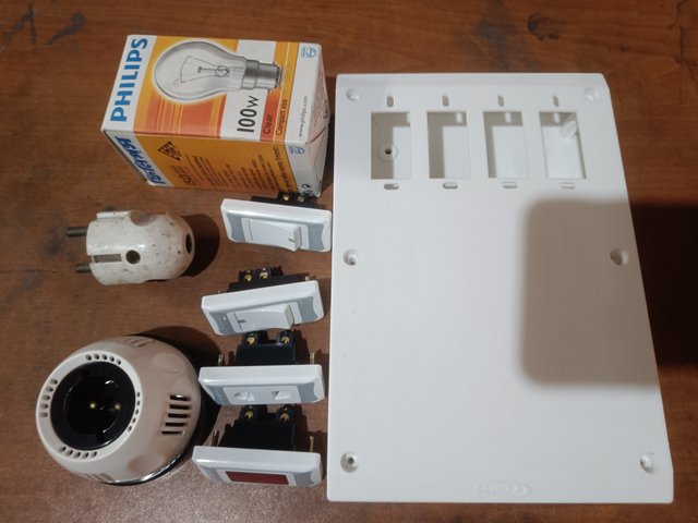
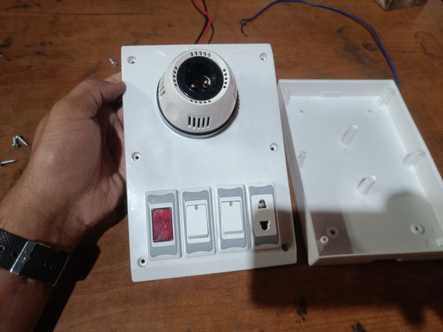
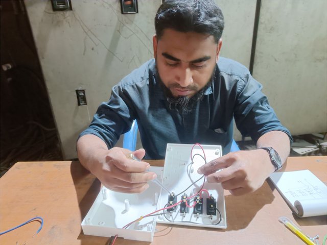
Then, I separated the top part of the PVC board. There are four holes in the upper part of the PVC board. I set up two one-way switches, a Tow Pin socket, and an indicator light. We will arrange our own. Then, I put them in the PVC holes one by one.
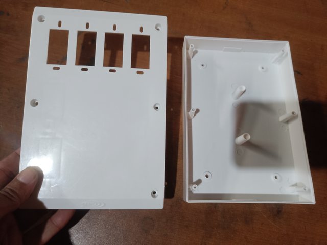
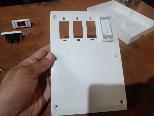
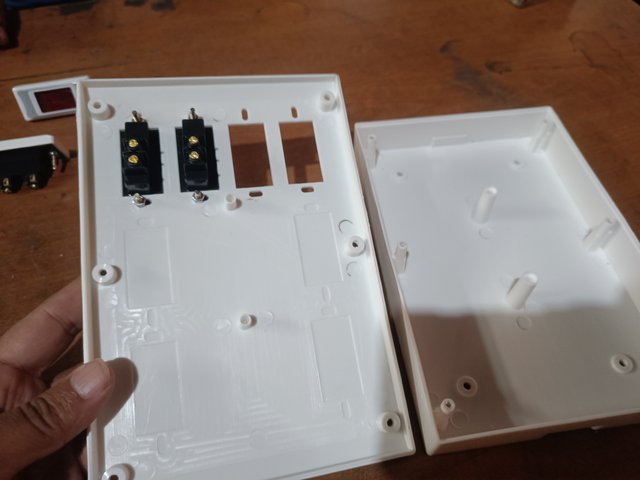
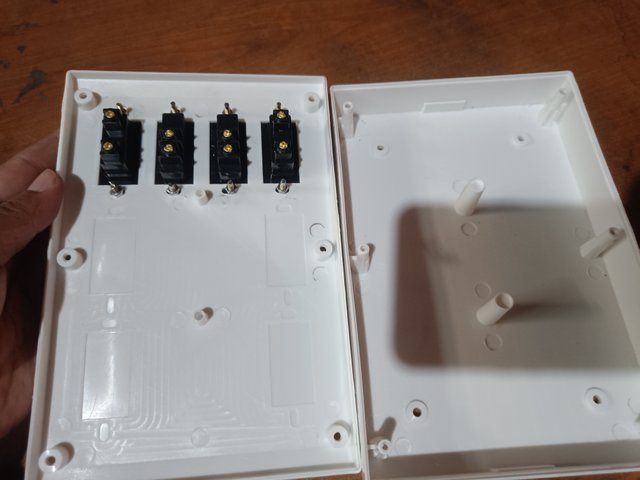
Then, I set up the baton holder on the PVC board and connected it with red and black wire. Then, I made a hole in the middle of the board. Red and black cables entered through holes in the board. Then, I set up the baton holder on the board.
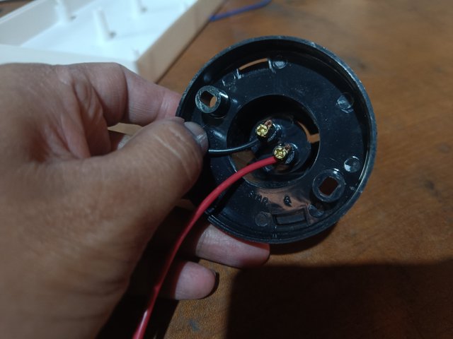
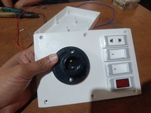
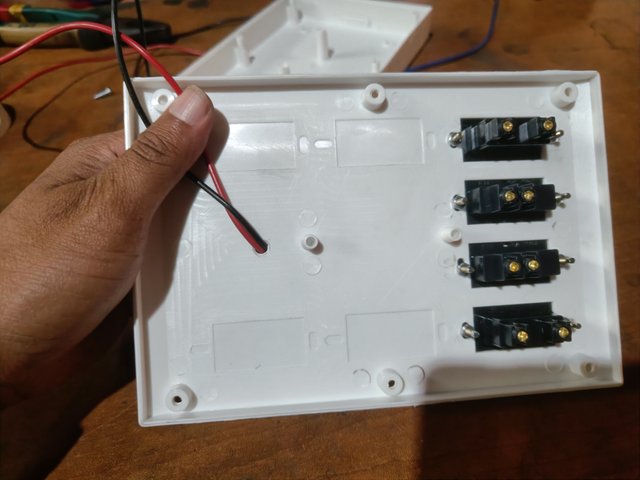
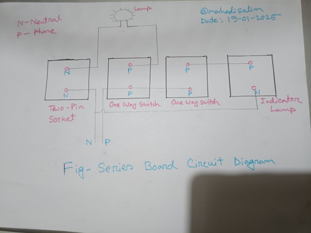
Then, I designed the circuit to make a series board. Then, I looked at the circuit and connected the switch, socket, indicator light, and baton holder. I have drawn the circuit according to the materials I need. You will draw the circuit according to your materials.
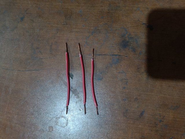
Then, I used red wire for the phase wire and black wire for the neutral wire. I see the circuit and connect each point with a red wire. I have shown it in the picture below.
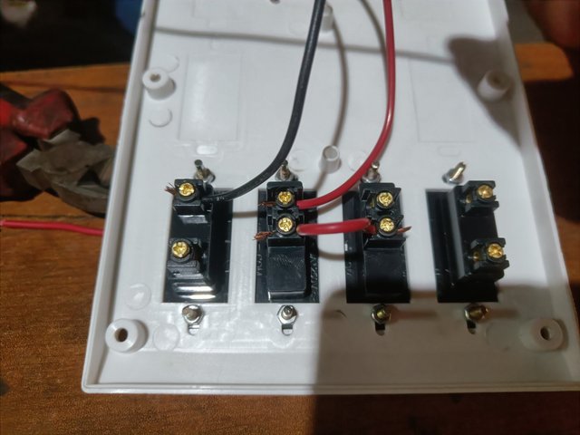
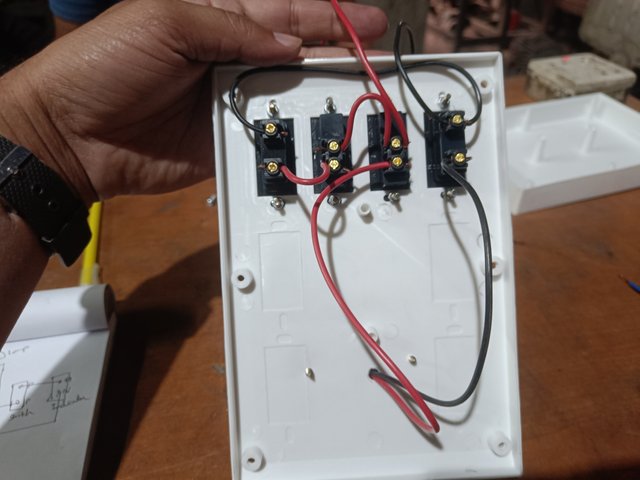
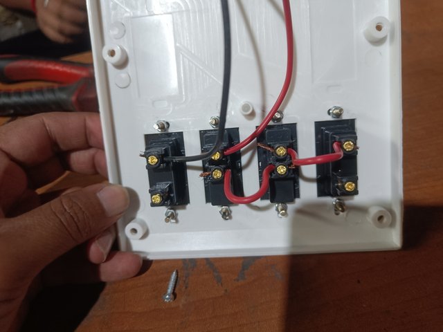
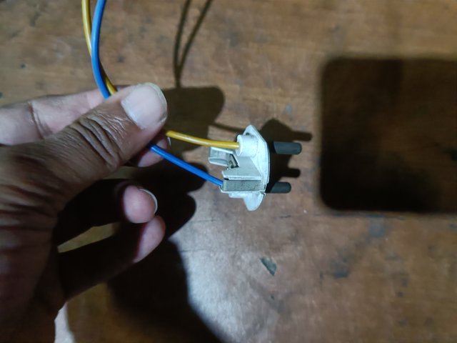
Then, I match the entire circuit to my drawing. Then, I connect a phase and a neutral wire to a two-pin plug. My series board build is almost complete. However, care should be taken while connecting the phase and neutral at their proper places.
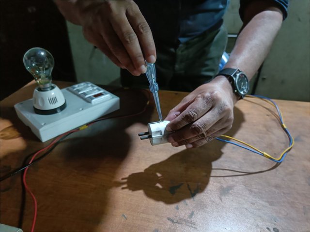
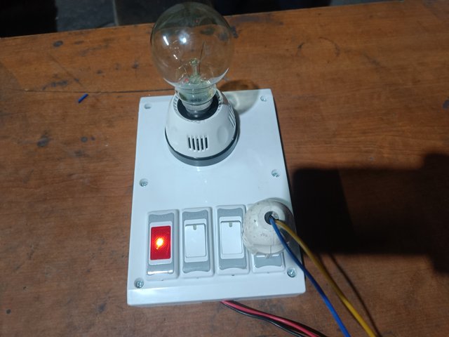
I will first supply power to the board. Then, I will put two of the two-pin sockets next to it, and the light of the series board will not turn off. When I connect the two wire ends, the lamp is lit. I knew my series board was built correctly because the light came on. Whenever I check the equipment, I will first connect the two wires and check with the series board.
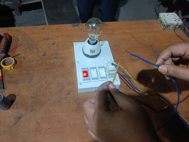
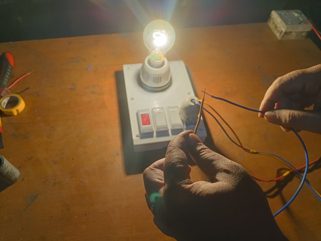
I'll check a capacitor in a ceiling fan in my house with a series board. I connect the series board's two wires to the capacitor's two ends. The lights on the serial board are not lit. Then I realized the capacitor I checked was bad. Even if the light is light, I will assume that the capacitor is damaged.
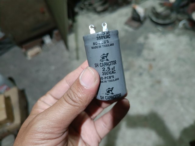
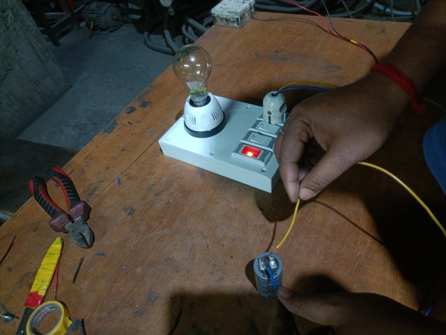
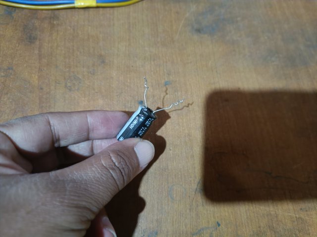
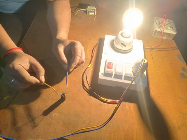
I take a 3.5 microfarad capacitor. Connect the two ends of the two capacitors of the series board. Then, the 100-watt light of the series board lights up. As the lights are brighter, I understand that the capacitor's quality is very good. Sometimes, if the value of the capacitor is low, the light will be low. I hope everyone understands.
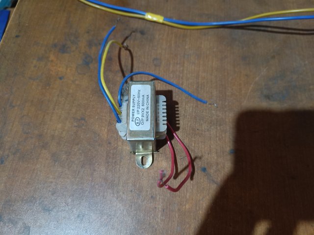
I remove the transformer from an electronics circuit. I will check the transformer with the series board. I connect the two wires of the series board between the two wires at the output of the transformer. The lamp on the series board gives a bright light. That means the transformer is good. If the transformer has a coil shock, the lamp will not light. I hope you can check the electronic component transformer with the series board.
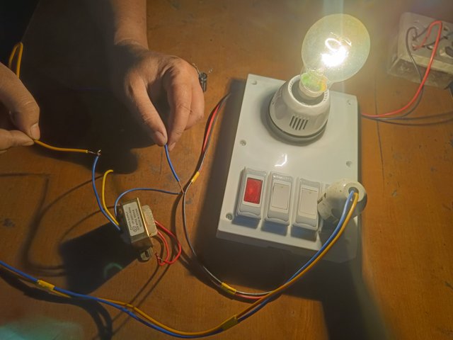
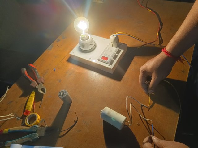
I collect capacitors from an electronic circuit. Then, I connect the series board's two wires to the capacitor's two ends. The light on the serial board lights up. I can tell by the brightness of the lights that the capacitor is good.
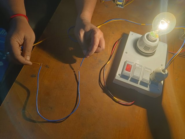
We can check the cable through a serial board. The cable insulation can be checked with a series board if cut inside. I check with a piece of cable. I connect the two ends of the cable on the series board. If the cable insulation is cut inside, the light will not light up. I see the light on, so I understand the cable is good.
I will check the field coil of a three-phase motor. We know that a three-phase motor has three wires. We will connect the two wires of the series board once to the red and yellow wires of the motor and then to the yellow and blue wires. If the light on the serial board is on, the motor is good.
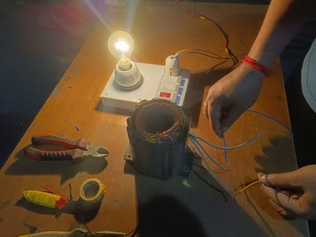
I have prepared lessons for my students on important industrial electrical topics for six weeks. Many thanks to the Steemitblog Team for organizing beautiful and informative learning lessons. I had a great time with the students. I wish every student of mine a bright future. I have left out some important points because electricity is a subject that never ends. This week, I was going to discuss the transmission and distribution of electricity. However, I was able to show students an important task this week. Making a series board is most important for an electrical student. All the best to my beloved students.
A. Make a series board and share the technique of making it in at least five steps with drawings.
[Note: Practical work is to be shared with your photos.]
B. Check with two electrical or electronic device series boards and show results.
C. Check with a short piece of cable in a series board and show the result.
D. I will award one mark for clean image and post quality.
Marks Distribution:
| Sl. No | Marks |
|---|---|
| A | 5 Marks |
| B | 2.5 Marks |
| C | 1.5 Marks |
| D | 1 Mark |
- Your title should be " Creating an Electrical Series Board."
- The content must be #steemexclusive.
- The article must contain the tag #electricity-s22w6.
- Homework posts must be at least 400 words.
- Plagiarism is not allowed.
- The link of your task must be added in the comments of this publication.
- Use the burnsteem25 tag only if you have set the 25% payout to @null.
- You can publish homework in any community and in any language. But don't forget to use the original tag.
- Invite three of your active Steemian friends.
- The participation schedule is between Monday, January 20, 2025, at 00:00 UTC to Sunday, - January 26, 2025, at 23:59 UTC.
SC01/SC02 would check on the entire 15 participating Teaching Teams and Challengers and upvote outstanding content. Upvotes are not guaranteed for all articles.
At the end of the week, we would nominate the top 4 users who had performed well in the contest and would be eligible for votes from SC01/SC02.

Best Regards,
Industrial Electrical Instructor
@mahadisalim


This is my Twitter share link :
https://twitter.com/mahadih83660186/status/1880919620842090764?t=jmDeipQvnF23PtjnSjumBA&s=19
This is a great week. Hopefully this week I can build a series of boards and achieve the ability to put them on display.