"SLC21/WK2: Introduction to Basic Electrical Circuits & Cable Joint."
 |
|---|
What is called an electrical circuit? Mention the importance of circuits in electrical engineering.
An electrical circuit simply put in a layman's understanding, means a pathway or a closed loop that allows the flow of electric current from a power source (station, supply) through various electrical components like inductors, capacitors, resistors, or any other devices and flow back to the power source (station, supply).
Conductive wires and components that create a path for electronics to generate electrical power that can perform work like powering a motor or bulb is what an electrical circuit consists of.
Importance
There are many important circuits in electrical engineering which I have only mentioned and briefly discussed the five that are the most important.
Foundation of Electrical System
Electrical circuits stand as the building block of all electronic systems and electrical. Also in addition to this, the circuits in engineering form the basis of almost all the devices that make use of electricity, beginning from household gadgets to other complex machinery in our home and office.Power Distribution:
It enables the efficient control and distribution of electrical power. This is very important in our homes, industries, and all infrastructures and machinery that depend on electricity.Automation and Control:
Circuits are central to automation which allows engineers to create systems that can control machinery and other automated systems.Signal processing:
In digital systems and communication, circuits process and transmit information through the help of electrical signals which is difficult in such as computing, data transmission, and communication.Efficiency and Safety:
The design of a circuit is to ensure that electrical systems operate efficiently and safely preventing overload, faults, or short circuits that could lead to loss of energy.
Mention at least two differences between series circuits and parallel circuits.
Series Circuit
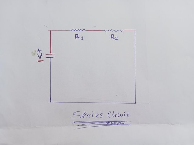
In terms of current flow the current flow in a series circuit flows (pass) through each component one after the others, and the same current also flows through all the components as well.
In terms of voltage distribution, it is divided across each of its components. Meaning the total voltage power source cut across the entire components.
Parallel Circuit
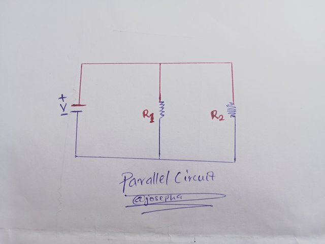
In terms of current flow the current in a parallel circuit is divided and flows (pass) through several branches, so that each of the branches can receive only a portion of the total current flow.
In terms of voltage distribution, the full voltage source is received by each branch, so that each component that is connected in parallel gets to have the same equal amount of voltage across the parallel circuit.
Note the above two circuits mention their names, and calculate the total resistance of the two circuits. Assume any value of R1 and R2 but not the value specified in the course.
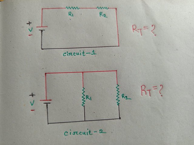
Based on the given information in the image provided by the professor, we can easily identify the two given circuits as; series circuit and parallel circuit.
In the series circuit, R1 and R2 are connected
Total Resistance (RT) is the sum of all resistance:
RT = R1 + R2
In the parallel circuit, the resistors R1 and R2 are connected in parallel.
Total Resistance (RT) is calculated using the given formula below.
RT = 1 / R1 + 1 / R2
Example, let's assume that the following for both series and parallel circuits is being given to us.
- R1 =10Ω
- R2 = 20Ω
For series circuit it would be calculated as shown below.
RT = R1 + R2 = 10 + 20 = 30Ω
For parallel circuit it would be calculated as shown below.
RT = R1 × R2 / R1 + R2 = 10 × 20 / 10 + 20 = 200 / 30 = 6.67Ω
Based on the given calculation we have illustrated, it then means the Resistance for each of the circuits is as shared below.
Series circuit (RT) = 30Ω
Parallel Circuit (RT) = 6.67Ω
Take two pieces of wire and connect them properly. Be sure to mention consistent images and clear descriptions.
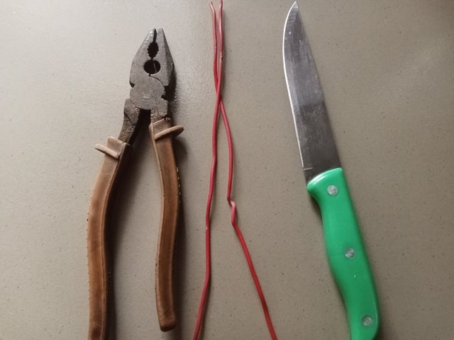
- Above you can see my wire, knife, and pliers.
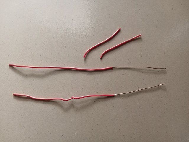
- I position the knife on the wire at an angle of 30 degrees and take the cutting.
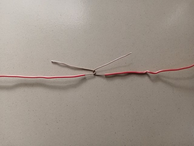
- I cut the wire insulation from the four sides at the same angle as shared in the image.
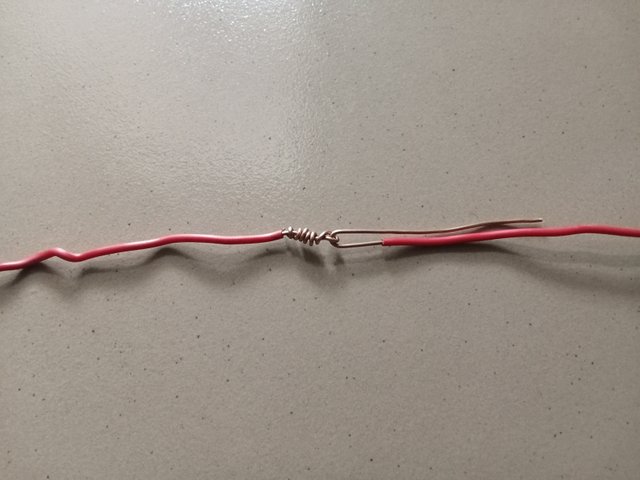
- After cutting, I then remove the insulation as I wish to make the joint which I only used 1 inch.
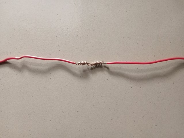
- I bent the wire from both sides along the middle of the two positioned one against the other and twisted the two extended parts in opposite directions.
After completing this lesson write what you learn in your own words
After completing this lesson I learned how to properly connect two pieces of wire I also learned about the functions and differences between series circuits and parallel circuits before the lesson I thought both served the same function but after completing this lesson I then noticed there are differences between them. The lessons have helped me to improve my understanding of electrical circuits and I can apply the knowledge that I have gained to real-life practicals.
I am inviting; @dove11, @simonmwigwe, and @ruthjoe
Cc:
@solaymann
Wow you must have really put in great work. Thank you for your great work you are actually doing
Thank you.