SLC21/WK2: Introduction to Basic Electrical Circuits & Cable Joint.
SLC21/WK2: Introduction to Basic Electrical Circuits & Cable Joint.


Hello Everyone,
It's @besticofinder here, and I'm taking part in this basic electrical cause organised by organised by @mahadisalim and @solaymann with great enthusiasm after following the first lesson last week. I'm really glad to see the selected topic this week , "Introduction to Basic Electrical Circuits & Cable Joint" which is one of the major aspect in the field of electrical engineering. Circuit theory, or the concepts associated with electrical circuits are very important on getting the quality of power output we need for the particular application. We can control the voltage, current and sometimes frequency and if we are dealing with alternating current we can change the phase of the voltage using inductive and capacitive components by changing the power factor angle. So if we are learning about circuits, it's really important to start learning from the basics.
Okay, let's start the homework of the lesson 02.
What is called an electrical circuit? Mention the importance of circuits in electrical engineering.
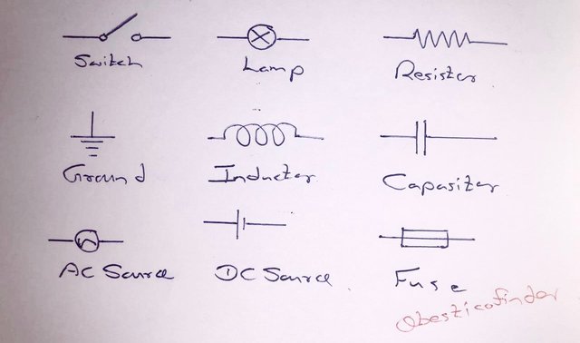
Electrical circuits can be defined in anyways, simply it's a set of electric components such as resistors, inductors, capacitors, sources connected as a network through electrical conductors. These electric circuits can be found in different levels, from simple electric circuits ( circuit of a torch, iron etc ) to a complex electric circuit ( utility grid, micro grids, power systems etc. ) In most of the electrical systems we can find the following components.

Basic components of an electrical circuit So these electrical circuit's are essential for three main components of electrical power , power generation, power transmission and power distribution and also at the user end, for every application we need electrical circuits to consume the electrical energy effectively and safely.
Why electrical circuits are important in Electrical Engineering ?
Electrical circuits arrange electrical components in an organised manners where electrical engineers get the opportunity to design , control and analyse electrical current flow according to a particular application.
With the help of electrical circuit engineers have the ability to manage electrical energy more efficency which will increase the overall power efficency of the particular application.
Electrical circuits improve the safety and reliability of electrical systems. As the power is well managed following the safety standards, there is very less chances of hazard situations. Also electrical circuits have components for safety such as fuses, MCB, MCCB, RCB, RCD, RCCB, Surge arrestors etc.
Electrical circuits enable engineers to troubleshoot the problems in a simple manner. As the circuit is arranged following a particular design, engineers can find the fault very easily.
Mention at least two differences between series circuit and parallel circuit.
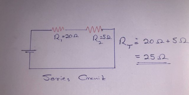
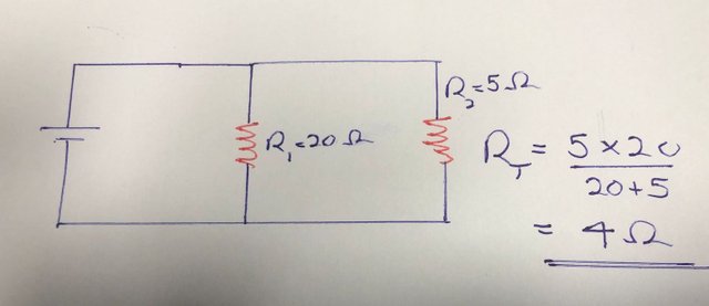
Note the above two circuits and mention their names, and calculate the total resistance of the two circuit. Assume any value of R1 and R2 but not the value specified in the course.
Differences between series circuit and parallel circuit ( considering resistor circuits )
There are many advantages and disadvantages of series and parallel circuits. I have listed some of the below.
| Point | Series Circuit | Parallel Circuit |
|---|---|---|
| Voltage | Resistors keep voltages based on their resistance value | Every resistor receives the same voltage of the power source |
| Current | Same current flows through each resistor | Current flows trough the resistor depends on the resistance value |
| Total Resistance | Total resistance increase when more resistors added in series | Total resistance decrease when more resistors added to parallel branches |
| Reliability | If one resistor fails, total current flow of the circuit fails | If one resistor fails, current continue to flow through other branches. |
| Fault identification | Easy to find the faulty location | Difficulty to find the faulty location |
I'm demonstrating the calculation of total resistance using a 20 Ohm and 5 Ohm resistor as below
Series Circuit

Parallel Circuit

Take two pieces of wire and connect them properly. Be sure to mention consistent images and clear descriptions.
Step 01
To practice the practical component of the lesson, I found a single core 1/1.13mm wire which is commonly used in Sri Lanka for domestic installations. I have my knife and my combination plier ready for the task.

Step 02
I started the work following the given instruction. First task is to remove the insulation of the cable. For that I used a knife as instructed and made angle between 30-60 degrees ( It was really easy that way , as insulation was sharply cut as I wanted ).

Step 03
Then I was able to disconnect the insulation like this and then I used my combination plier to drag this insulation part.

Step 04
So my first part was successful. And I used the same procedure for the other cable. I was able to clear insulation of both cables nicely.

Step 05
Then I bent the conductor from 90 degrees and positioned one against other which made the contact very solid.

Step 06
In the final step I followed the exact instruction given. I twisted the extended copper conductor paths for opposite directions.

After completing this lesson write what you learn in your own words.
I must admit that even while leaning circuit theory when I was an undergraduate, I didn't think this deeply about series and parallel circuits. And I was able understand many new things when I'm refereeing to literature to participate the contest regarding the circuit types. I also had the opportunity to learn about series-parallel ( combined) circuits.
The instructions provided to learn how to connect two cables were perfect. I was able to follow same steps using simple tools and I was able to get a very good results. I must admit, generally, the issue with connecting two cable is when the cable is under a tension, it sometimes breaks with the joint. But with this technique as two conductors are oppositely jointed there is very less chance of breaking the joint.
Also another issue in cable joints is high resistance, but as the external parts of the cables are twisted well around the other conductor, there is more contacted surface area, thus it will reduce the resistance.
Thank you for the all the knowledge shared and this lesson is very important for anyone. This is a skill everyone must develop. So thanks again. I'm waiting for the next lesson.
-Vimukthi Vithanage
I like to invite : @vishwara @virajherath and @nishadi89 to join the contest.
-Vimukthi Vithanage


Vimukkthi Vithanage (@besticofinder) is an Electrical Engineer and a Lecturer by profession , crypto enthusiast and a person who always values his freedom. He loves traveling , teaching and to spend time with his friends. A good reader and a good listener. He currently works in Faculty of Technology , University of Sabaragamuwa , Sri Lanka and also as a freelance SEO service provider. He writes on different topics related to his daily activities. If you like his writings , don't forget to show your love with an upvote and leave a feedback to show more love. And a resteem will be a great encouragement for his work. Feel free to contact him on discord anytime . He always love to make new friends.
Check his latest research work : visit

Your first point is accomplished with great detail. You have added extra talent in a nice way which I really appreciate. You have given a great insight into the basic elements of electrical circuits and their names. Explains the definition of circuits and their requirements clearly. (1.5)
The differences between series and parallel circuits are very well presented. Each difference is clearly stated. Especially a specific topic, current, voltage, power, error is presented separately, so I enjoyed reviewing your post.
You are Drawing the two exact circuits mentioned and calculating the total resistance of the circuit taking their different values. Circuit diagram and calculation of total resistance solved clearly. (4)
You have done point C correctly. Here you have connected two pieces of wire in series which is very consistent with the competition lesson. The consistent activity of your cable joint proves you were very focused. (3)
Finally, what you learn from Basic Electricity Lesson 2 has inspired us even more. You have presented the points you learned from this lesson in your own words. (1.5)
Comment/Recommendation
Dear @solaymann,
Thank you very much for your detailed evaluation on my post. Actually I really enjoyed taking part your basic electrical engineering course and also gave my lot of new knowledge from other authors. Actually from last week post I notice 4 different types of domestic socket outlets which was totally new thing for me. I never expected 10/10 , I'm really happy. Thank you again.
-Vimukthi
Great presentation! Explained the important points of electrical circuits in very simple language. It is very useful for new students. Thanks for such a wonderful post. Good luck for the contest.
Thank you very much for your kind feedback !