Microcontroller: Using ESP to Control Electrical Outlets from a Web Page
Why not delegate predictable tasks to a microcontroller? As an introduction to microcontrollers, for this demonstration, I programmed an ESP8266e wireless microcontroller to control household electrical outlets from a web page. The web page can be accessed from any computer, phone, device, or server that can access a web page, and has access to the router that the ESP8266e is WiFi connected to. How the microcontroller operates depends on how it is programmed. The digital thermostat that turns my freezer into a fridge is an example of a pre-programmed microcontroller. It has a temperature sensor probe that goes inside the freezer. A built in relay turns on or off the plugged in freezer as needed - to keep the fridge at the requested temperature (2'C).
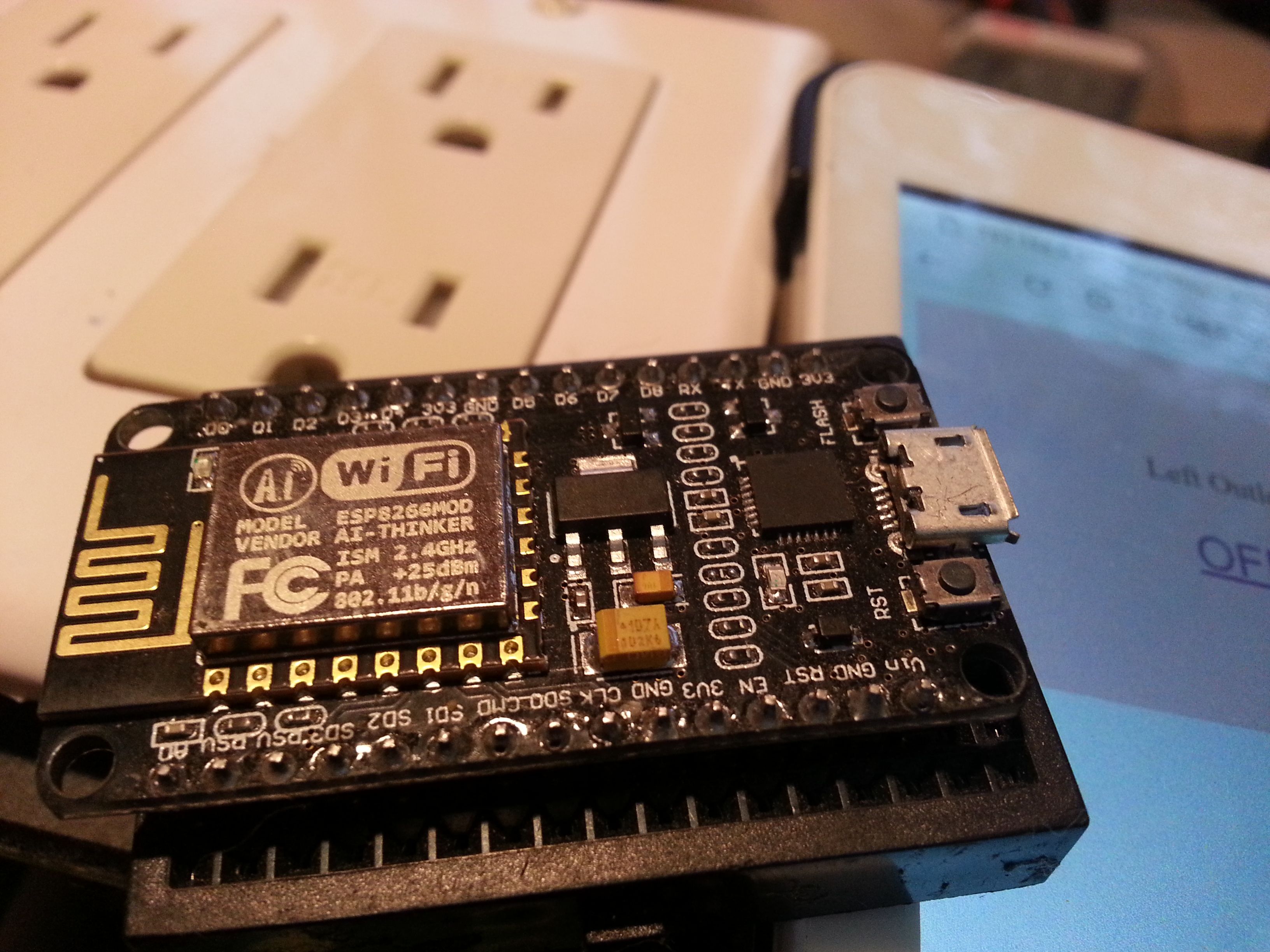
I started programming microcontrollers so I could design more complex control systems that are not available for purchase. An irrigation system that gets the weather forecast from the Internet and holds back on irrigation - if there is rain coming - is one of my planned projects with the ESP. A greenhouse with automatic irrigation when the soil is dry and turns on a solar powered fan or opens a window when the temperature gets too hot is another potential project. There are a lot of smart home system products out there, I would prefer to build my own so that I would be sure that only I had access to the system. Microcontrollers can also control motors, servos, and sensors for robotics.
Quick Introduction to Microcontrollers
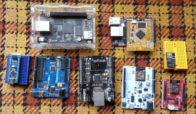
Microcontrollers can read electronic sensors like buttons, switches, joysticks, temperature, pressure, moisture, voltage, direction, movement, heat, gasses, light, and more. They can also control micro-electronic items such as LED lights, servos, motor controllers, relays, and display screens. The microcontroller communicates with sensors and hardware with very small amperage - milliamps or mA. There are 1000 milliamps in an amp. The amperage output of a micro-controller is too small to turn on a household light bulb, but it can control a relay that is like a light switch that can be controlled with milliamps of electricity.
Arduino IDE - The Programming Environment for the ESP8266e
My experience with programming microcontrollers started with the Arduino. The Arduino is programmed with the Arduino IDE - a programming environment with a language similar to Java. Many other microcontrollers have made their board files available to add to the Arduino IDE. The ESP8266e is one of these boards that can be programmed with the Arduino IDE.
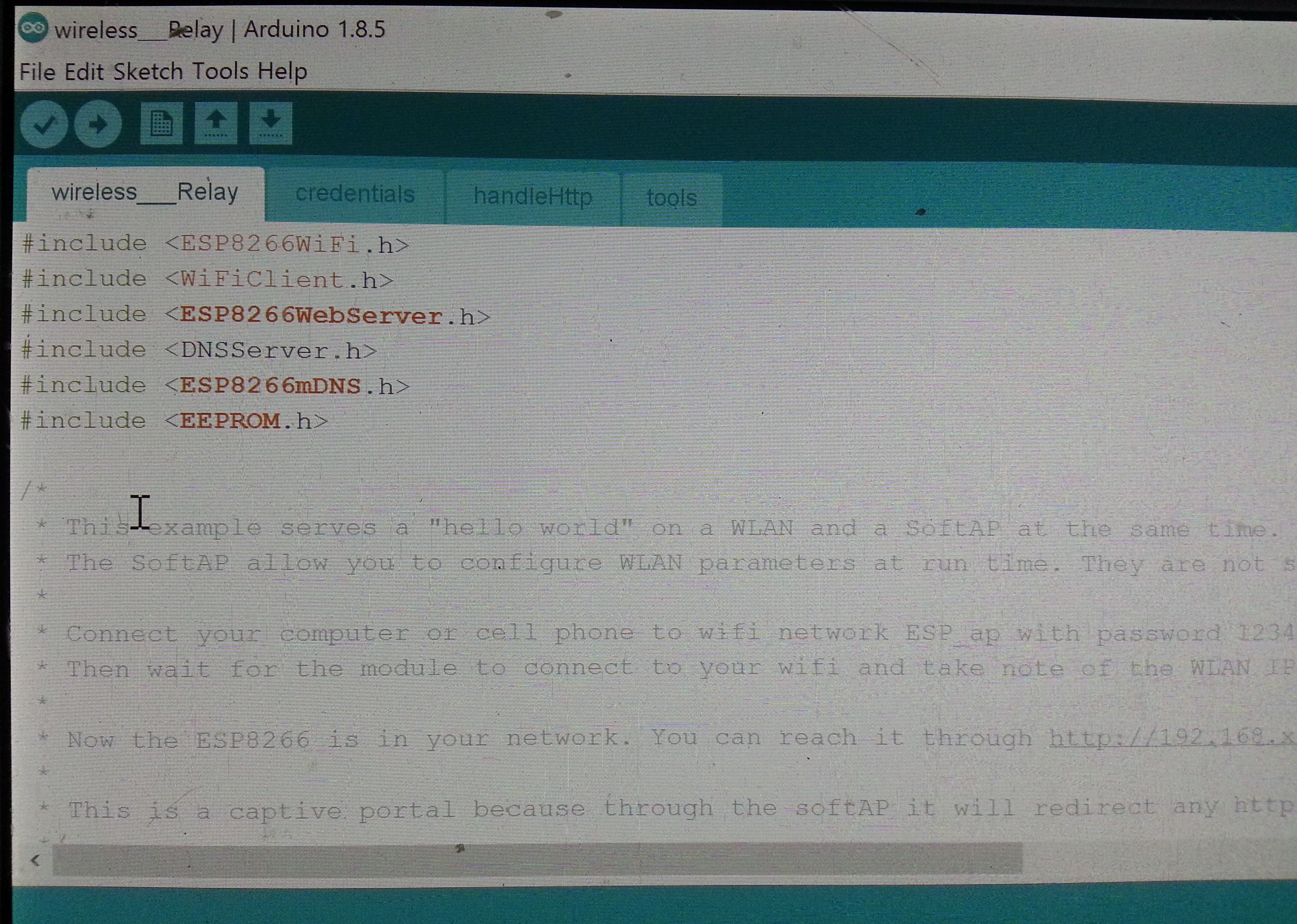
The Arduino IDE has many Libraries that people have shared and added to the IDE. Libraries are programs or a set of instructions for common tasks that someone has already written. When I need to add WiFi to the new program, instead of re-inventing the wheel by typing in many lines of code, I just add the library. In the picture above you can see the libraries that this example program needed to #include. Most of the libraries in this program or 'sketch' have to do with the WiFi connection - accessing the Internet and web page serving.
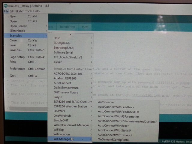
Libraries also come with example sketches that can be used as a starting point for a new program, see the picture above. The code from a sensor example sketch can be copied and pasted into a WiFi sketch. This makes creating new sketches or programs much easier - assemble the pieces, then modify for the new program as needed.
WiFi Wireless with the ESP8266e
The ESP8266e is a wireless microcontroller. It can automatically connect to a WiFi router, provide a hotspot for direct connection and configuring. It can also team up with other esp8266e micro-controllers to make a mesh network where the devices relay messages to each other. The ESP8266e is also relatively cheap - 2 for $10 on amazon.com.
ESP8266e Microcontroller Hardware
Below is a picture of a ESP8266e plugged into a small breadboard. The breadboard has jumper wire pin holes for the ESP pins to plug into and are connected to the pin holes just beside them - for the easy connection of sensors and micro-controllable hardware to the microcontroller. The snake shaped copper on the left is the antenna, the silver box just to the right of it is the processor of the microcontroller. On the far right is the micro USB plugin for supplying 5 volt power, for connecting to a computer for uploading a program, or to communicate with the microcontroller through a serial terminal.
Across the row on the top you can see the D0 to D8 pins, these are the digital ins and outs of the ESP microcontroller. The TX and RX are the send and receive pins, along with the 3V power supply and the ground beside it makes the UART1 Serial Programming Header. The extra 3V and Ground in the middle of that row are for powering connected digital inputs and outputs. Unlike the Arduino that operates at 5 volts, the ESP operates at 3 volts. Any digital inputs must be no more than 3 volts or you risk damaging the microcontroller.
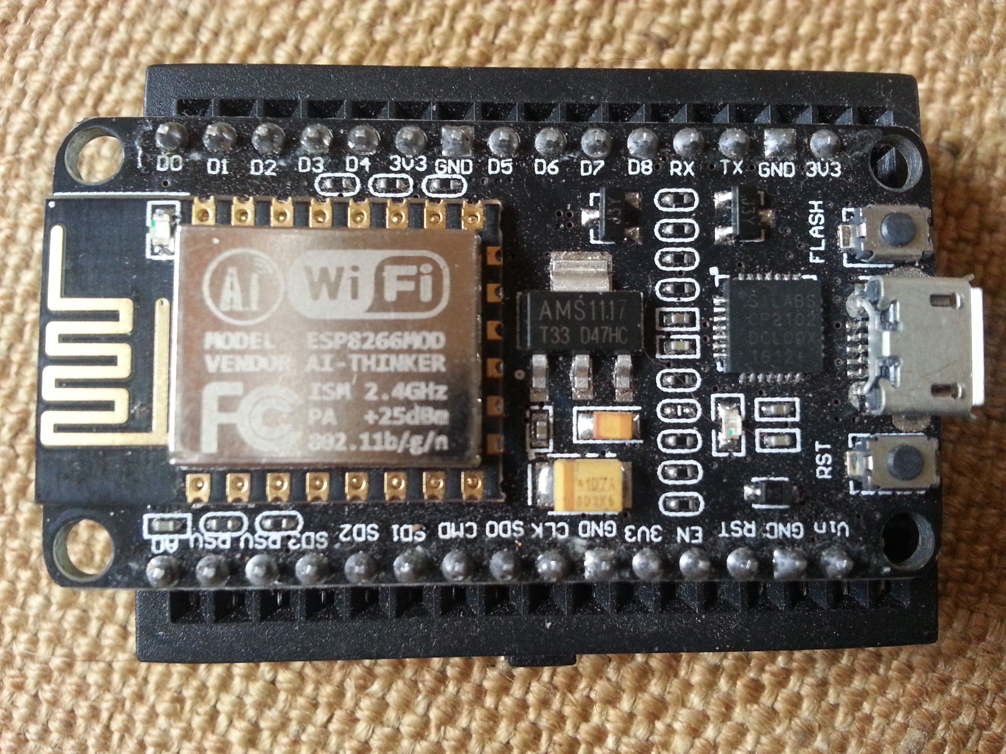
On the far left of the bottom row of the input and output pins in the picture above, you can see the A0 analog input. Digital inputs can only read on or off while the Analog input can read a range of values. Light and Voltage sensors are examples of analog input sensors - the sensed voltage level can be converted to 0% to 100% for light, or 11 volts to 16 volts for voltage, for example. The analog input range on the ESP is only 0v - 1v, so it's not as precise as the Arduino's five 0v-5v analog inputs. The Vin pin is the Voltage-In pin. If the ESP is powered with the Micro USB input, the Vin pin will output 5v. I use this to power the 5 volt double relay switch. The ESP can also be powered with a regulated 5v through the Vin and the ground to the GND pin.
Arduino IDE simple program structure
In the picture below you can see the sketch of a simple Arduino IDE program. There is no need to #include libraries at the top of this simple sketch. After the #include library declarations would be the variable defining. This carves out a place in the ESP memory to store the defined variables. In the picture below you can see I defined a variable and gave it a value of a Relay pin location - D5. Each line of code in Arduino IDE is ended with a semi-colon ( ; ).
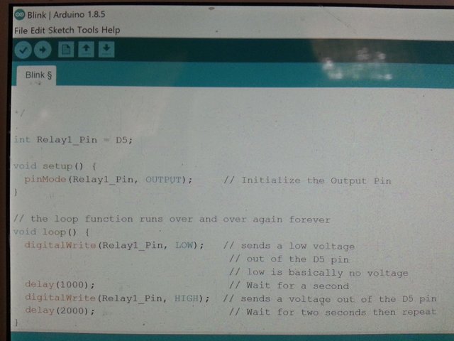
In the picture above you can see the Setup section enclosed with { } brackets. This is where you can give values to declared variables, setup input and output pins, and setup up libraries. Next is the Loop section that repeats indefinitely. In this simple example the relay receives no signal, waits 1 second, then sends voltage to the relay for 2 seconds, then repeats. Think of a car turn signal blinker, you can hear the relay clicking over.
What is a Relay Switch?
A Relay is like a light switch - not controlled by the finger, but with a low amperage electrical current. In this case from a microcontroller.
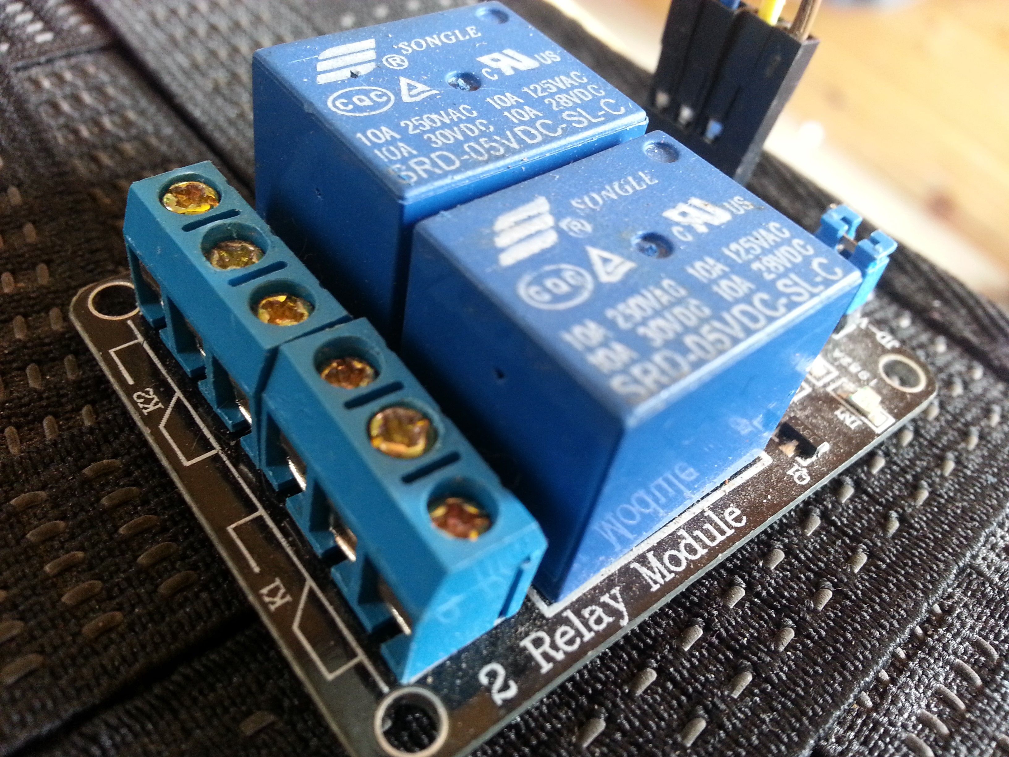
You can see the double relay switch with the wire connection posts for connecting the higher voltage electricity. Looking at one of the relay's set of three posts, the electricity supply wire goes in the middle. If the wire that goes to what needs to be switched on or off is inserted - and clamped down with the post screw - into the post to the left of the middle one, then the switch will be off until power is applied. If the wire is inserted and clamped down in the post that is to the right of the middle, then then switch will be on until low amperage power is applied to turn it off.
Connecting the ESP8266e to the Relay Pair
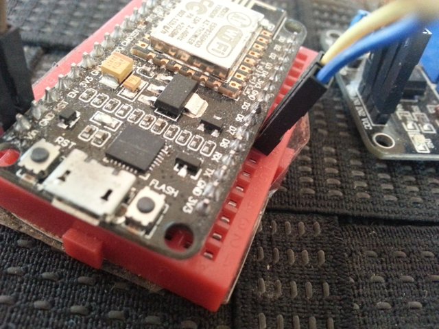
In the picture below, the 5v Vin and Ground on the ESP are connected with jumpers to the VCC and GND on the double relay. The digital pins D5 and D6 on the ESP are connected to the IN1 and IN2 of the double relay.
Compile and Upload the Web Page Controlled Relay Sketch to the ESP8266e
After a sketch is programmed to you liking, it is compiled or translated in to simple stream lined machine language that the selected microcontroller board can understand. If the sketch or program doesn't compile and results in an error, then any errors in the sketch need to be fixed. After a sketch has been successfully compiled, the next step is Uploading to the board over the USB cable.
In the video demo below you can see the USB cord attached to the ESP get plugged into the PC. I make sure the Communications Port from the Tools pulldown is set to the COM3 that appeared after plugging in the USB. I also double check to be sure the correct ESP microcontroller hardware is selected. For this ESP8266e board, the correct selection is NodeMCU 1.0 (ESP-12E Module). I have to be sure - there is a wide variety of microcontrollers that I work with.
Video - Arduino IDE Compile and Upload Demo
Uploaded Program Testing
Below is a video - testing the web page controlled relays. I want to be sure the program is working as expected before I pack all the parts into a small box.
The Project Build
In the picture below you can see the parts of this project ready for assembly.
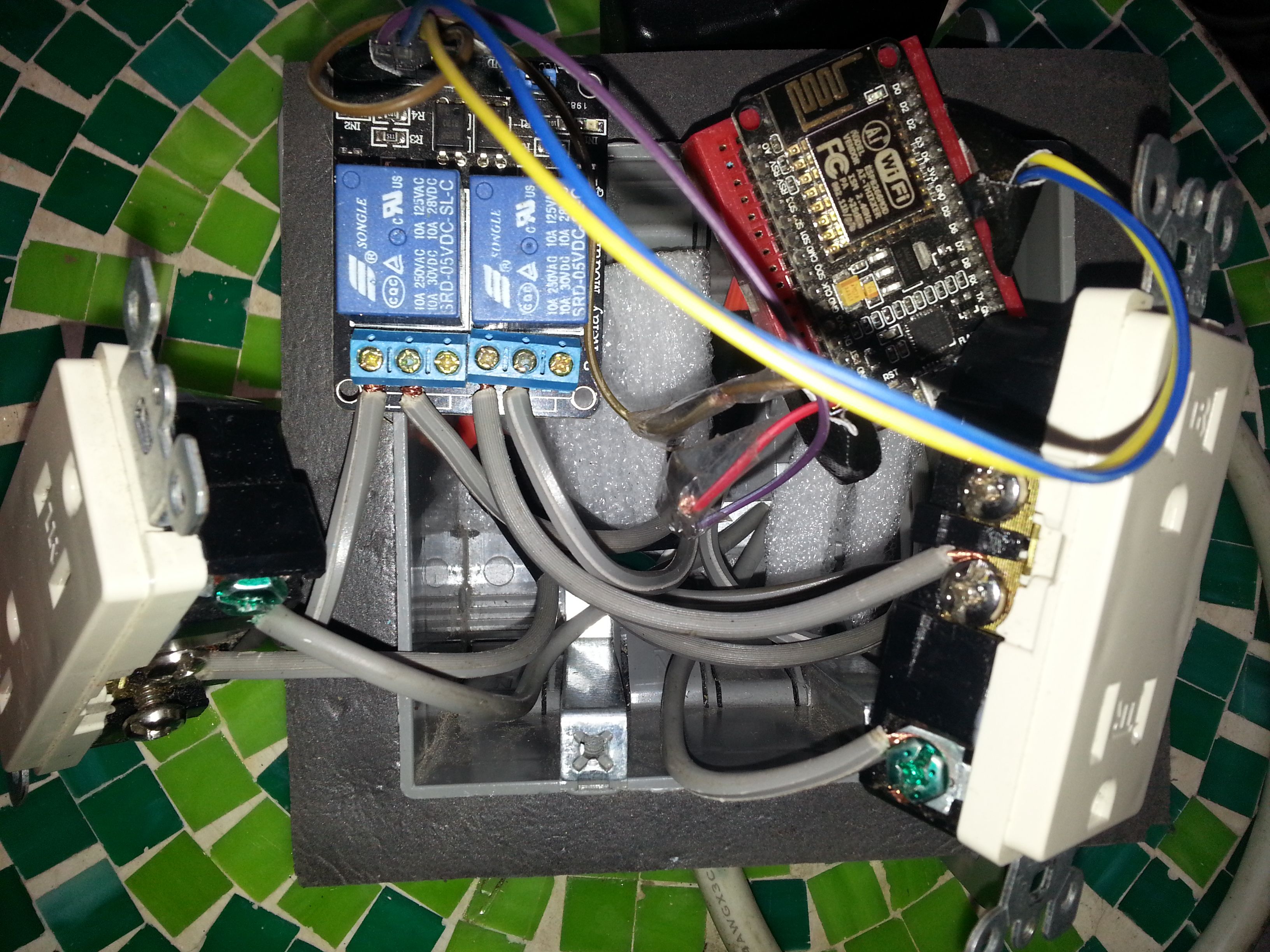
Be Sure You know about electrical wiring before you attempt any electrical project. Household electrical voltage can be very dangerous. Be sure what you are wiring is unplugged or the breaker turned off. Even if the device is unplugged there can sometimes be stored up power in internal transformers and capacitors.
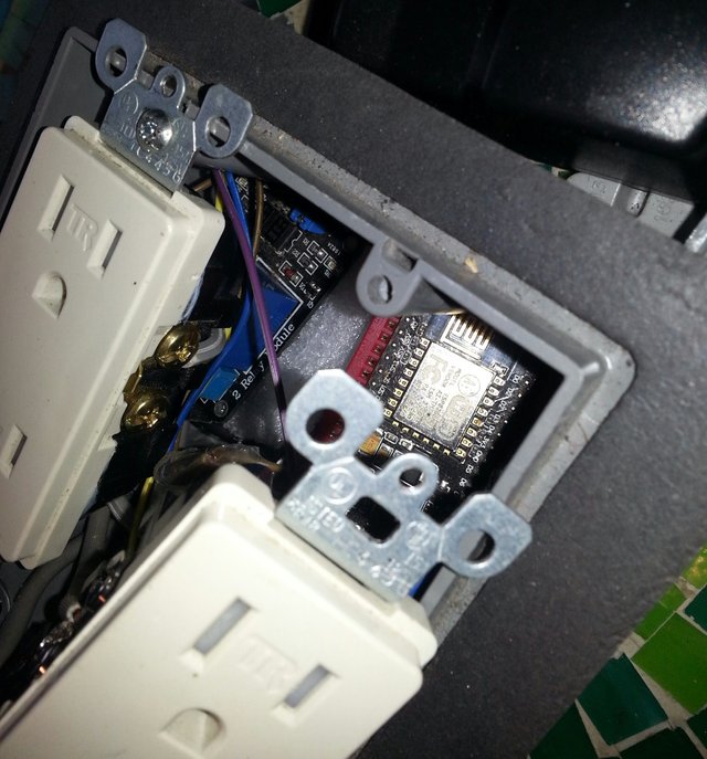
Finished Project Testing
Below is a video of the final project testing.
Many Possible Additions
Microcontrollers can be programmed many ways. In the picture below you can see a variety of sensors and switches that I will be using for upcoming projects that will be posted. I will go more in-depth with the programming details in the weekly microcontroller posts.
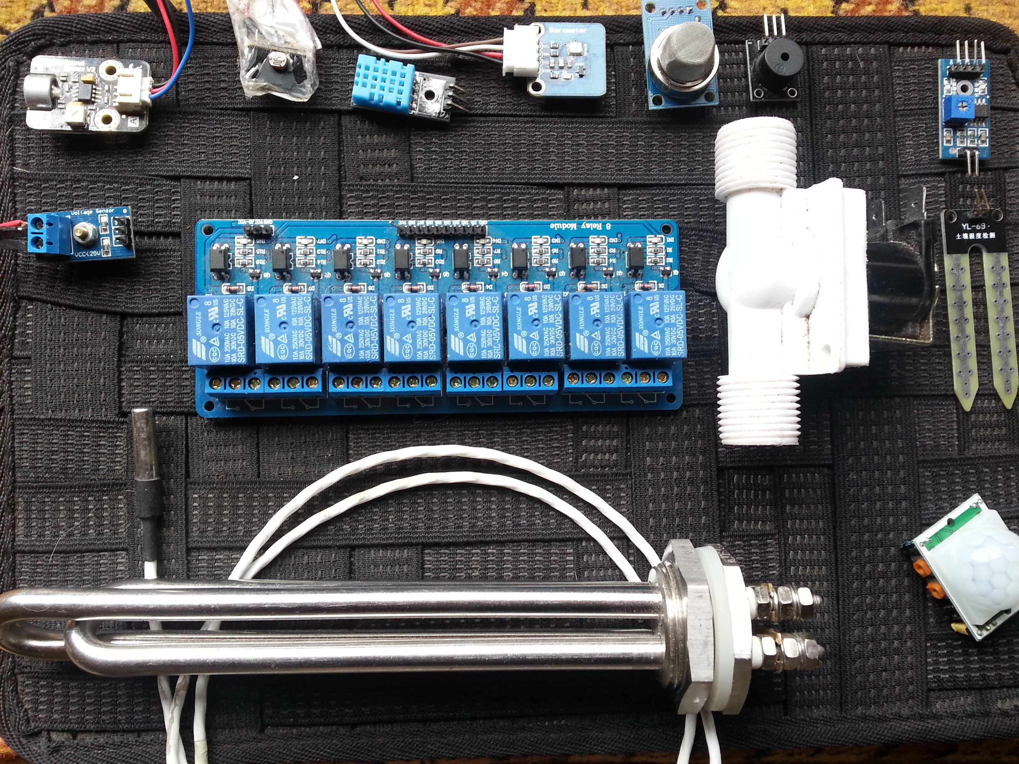
In the picture above, the top row: Sound sensor, Light sensor, Temperature/Humidity sensor, Barometric Pressure/precise temperature sensor, smoke and gasses sensor, and noise maker/beeper. In the center you can see the 8 relay switch block, to the left of that is a voltage sensor. To the right of the relay block is a water valve switch, to the right of that is a moisture sensor. Bottom right is a motion sensor, to the left is a water proof and high heat probe temperature sensor and a 300 watt water heating element that would be switched on with a relay for when there is ample power from the sun on my solar panels.
Setting up the Arduino IDE programming environment for ESP8266e:
sparkfun's how to install and setup Arduino IDE for the esp8266e
Zipped Files from this Project - for the Arduino IDE:
Have a great day!
Very cool project. Have you worked with a raspberry pi before? I have the raspberry pi3 but have not done much with it yet. I'm looking to make it into a retro pi. I'm also attempting to learn some electrical engineering on Khan Academy. It's a slow go but hopefully i will make some progress soon.
I have a pi3, pi2, and a burnt out pi1. Used the pi2 for xbmc media player sometimes. Have the cameras for them, played alot with motion capture, opencv, and speech recognition, but enjoyed the pi most as a headless server that scraped news and weather from the internet. It would collect and chart data from the microcontrollers, and act as the main interface for their data and control. Retro pi would be fun too, i never got around to trying it out, but i did get the ps/2 controller hooked up to the pi.
Thanks @geekgirl - it's always nice to see you. It feels good to be noticed :)
Now this is something I'd like to try someday. Looks like more of an electrical job than a programming one though.
With this simpler program, most of my time did go into the build. Even on the program side most of my time went to playing with the html for the web interface. The programming will get much more involved moving forward from here :)
Very useful information, my friend. This is definitely something needed when living a self-sustainable life. There is always plenty of work, so as you say, why not delegate some out.
Thanks @notconvinced - I'd love to see a post about the electric bike you built, i had an ebike for over the summer, but it wasnt powerful enough for these valleys I live in, it was easier for me to ride my mountain bike than to push the ebike up the hills :)
Wow man.. Good co-ordinated routine... Waay too technical for me.... i'd probably do it wrong and blow something up..
Credit to ya though it looks like you've got it sorted there.
The most dangerous part would be the household electrical wiring, but if someone knows how to wire a househould outlet safely then they would be most of the way there. As far as things burning up, I admit i've burned out a couple microcontroller regulators and a raspberry pi - i can still smell the electrical board burn smell and hear the pop of the regulator :)
Hey I get my Pi on monday cant wait.
Ah nice man - great little server, and most of the digital sensors and displays you can hook up to it :)