Dev Diary Part 18 - Modeling the Landing Gear of the F-14D Tomcat [2] w/ Motion Rigging
Yeah this is something else! The next installment in my journey of modeling and rigging the landing gear of the F-14 Tomcat [High Poly 3D model].
Step 1
.png)
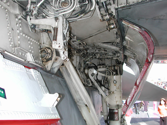
My favorite main landing gear and probably one of the most complex ever designed. I'll have to rig it in Blender in order to be able to finish the hard surface modelling. Reason being is I cannot rotate and tilt all objects in a realistic fashion without rigging. Also it'll have to be bone rigging because a rig controller wouldn't be feasible given the animation complexity. So far so good.
Some details:
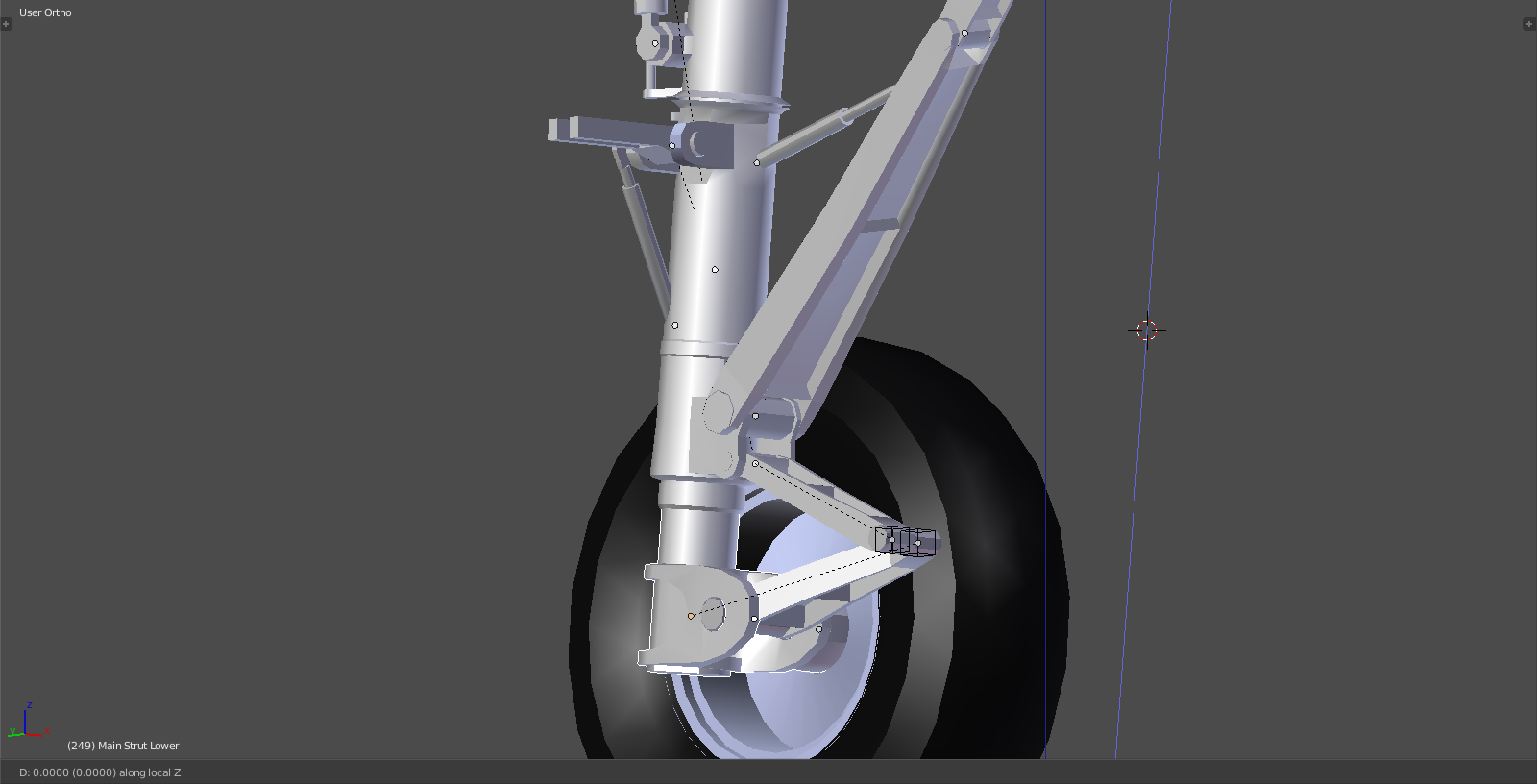
The only 'static' rotation component is the main landing gear upper strut < fuselage connection point 1
The main landing gear strut damper fully extends out after takeoff and fully extends the two lower control arms < this is where the wheelhub/bearing is attached to
The lower strut part rotates roughly 90deg inward when retracting
The main strut support beams fold in half, lower and upper part stay with the main strut but the assembly point on the fuselage is a rotating design < fuselage connection point 2
The main strut hydraulic actuator assembly also rotates along two axis (!) < fuselage connection point 3
The blocking T simply folds down 90deg and also stays with the main strut < fuselage connection point 4 (only when gear is down)
Yeah I know...pretty insane.
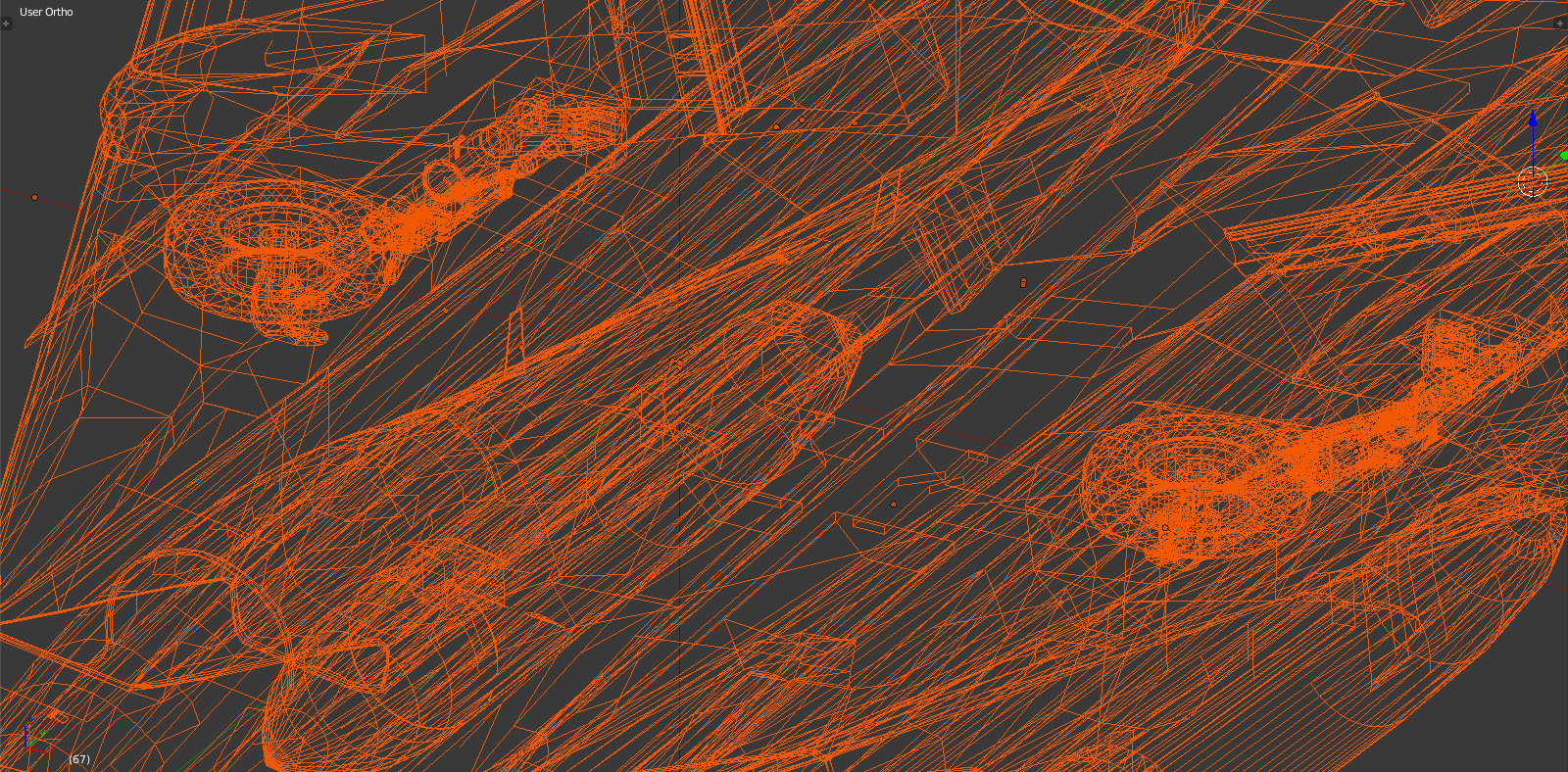
Step 2
.png)
Been working on the landing gear as the last big hurdle standing . The nose and main landing gear doors and fuselage parts have been separated from the main fuselage and all parts have been parented accordingly. I've added some orientation transformations as to be able to move parts at the correct angle such as main strut lower part 'sliding' out of the upper part.
Also in order to finalize hard surface modeling on the gear and the fuselage parts I'm rigging the landing gear simplistically with empties, constraints, parent/child relationships and manipulating object origins as pivot points. This can all be exported to 3DS but of course once there the plugin will have to be used to redo it in detail.
Currently some of my control arms are not tracking to the empties (scissor arms on bottom and main support beams on top) as they should. Still looking for what the problem is but should be resolved soon.
Step 3
Alright guys, small update on the landing gear rigging process. As stated before this is necessary to finish hard surface modelling and ensure scale, fit and proportion.
The following is very dry, will be boring to most and there are no fancy animations yet BUT to a tiny minority it might be quite interesting .
After trying with empties as constraints and some other 'non-bone' rigging I decided that I need an armature and bones rigging to make it work.
For anyone who doesn't know what this is, basically you use rigging techniques designed for organic, deforming objects (like a human hand) and apply it to non-deforming mechanical assemblies.
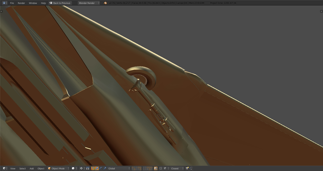
Current status:
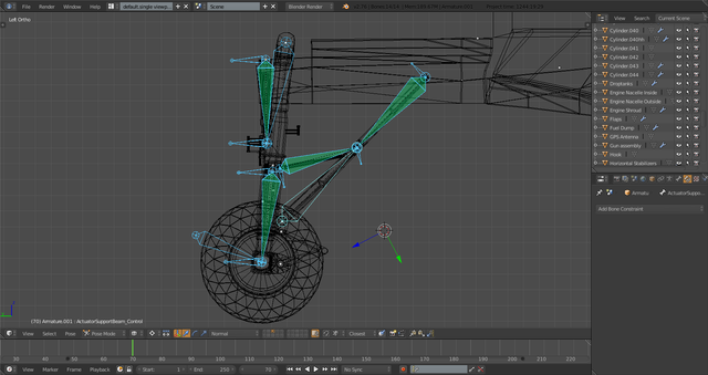
What you see is main strut actuator piston that rotates the entire MLG on top left, main strut piston on lower left, support beam rig on the lower right. I'll go through this in the following. The structure is always a bone with tip and base and a control bone that determines the position of the tip and thereby extends/retracts a piston.
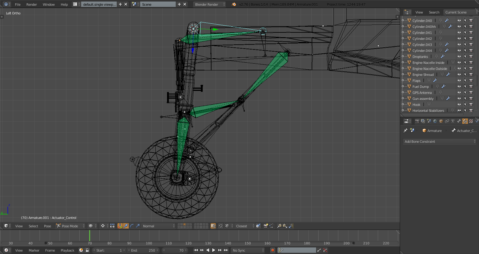
Note the control of the main strut actuator rotated to the 'retracted' position and the actuator bone extended. This rig will connect to vertex groups and result in the piston extending out of the base as would be the case in RL.
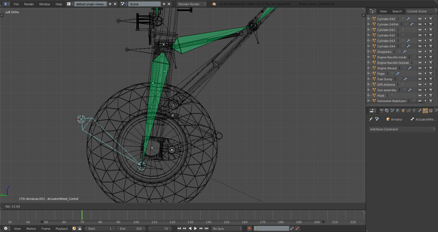
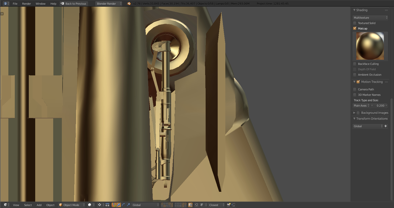
Working on the main strut, you can see the tip which will attach to the wheelhub part extend. Haven't decided on where it makes most sense to attach the control bone as it simply extends out and down on the local Z axis.
Now this is something special. Simple stuff is the piston that operates the lower part of the support beam retracting. Now you have the upper part of the support beam extending which it shouldn't do as it is a solid object.
Thing to remember is the two parts have the same length. Blender allows you to assign objects also to the control bone. So I'll assign the lower part of the support beam to the control bone which is solid and simply rotates and then compensate the extension of the upper part by rotating the entire assembly up thereby keeping the length of the upper beam constant.
It'll be evident once I have the animation done.
Now I 'just' have to finish the armature in terms of parenting it accordingly and then AND THEN have the lower part of the strut (where support beams, wheel and lower scissors as well as blocking T are attached) rotate inward as the assembly rotates upward.
Fear the Bones, Baby. - pun intended
Step 4
And I ran into the first problem, the kind I was hoping to bring out with the bones exercise. As you can see the support beam geometry is off. They're supposed to fold like a scissor and then jointly move up with the landing gear.
The upper part is attached to the fuselage in RL and is fixed here as well (at the base), both parts are locked in size and cannot deform and they track each other. In and of itself this system works perfectly.
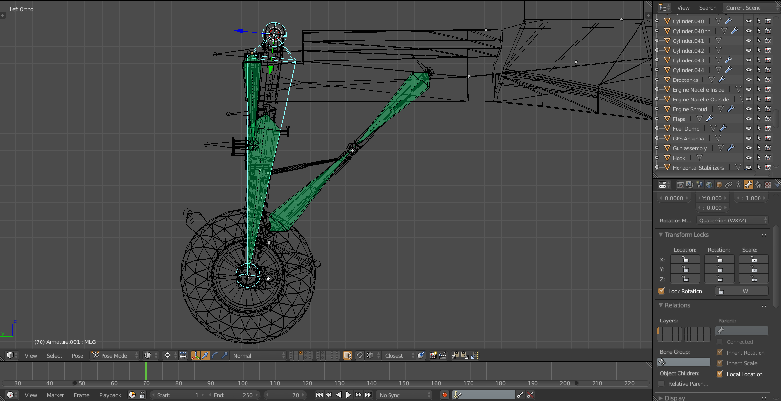
Through parenting the MLG moves up and the main actuator extends as it should, the lower beam folds toward the MLG and the upper beam tracks it BUT as it moves up the folding stops to work because
a) location of fuselage pivot point of MLG or beam or both is/are wrong
b) the beams have the wrong size
c) all of the above
Back to the drawing board . I might play with the bones until I have a setup that works and then modify the objects accordingly or really just do a tech drawing and calculate the positions and use that as a basis. The blueprints don't help here.
Step 5
Echoing on this issue this video is quite interesting and I use it for reference:
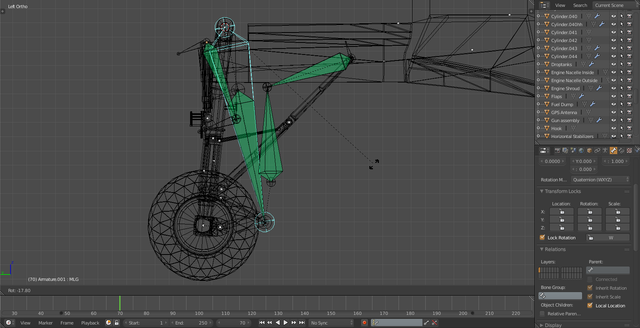
Note how the problem I describe above is manifesting here. The guy solved it in that he left the upper beam attached to the lower one and at half time you can see how the upper one folds and thereby 'disconnects' from its pivot point on the main fuselage. Looks like he's having the beams track to eachother without deforming which is how I did it as well. The rotation is beautifully done in this example.
This is an interesting solution but I plan to modify the model in such a way that it folds AND stays in place. Parenting the upper beam to the main strut while leaving it in global space makes sense and with the right proportion should work in terms of folding. More to come...
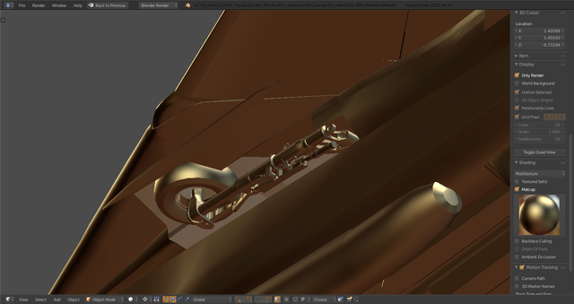
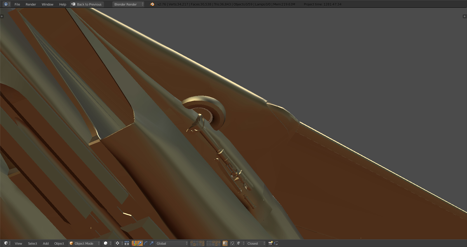
.jpg)
You can see the ball bearing in the picture above. The cool thing is when the geometry works without cutting into eachother the rigging should take care of the rotation by locking the lower beam's rotation to the local y axis, parenting it to the main strut and then leaving the upper one without lock and simply set the base of the rotation (on all axis) to the global pivot point on the fuselage. That way when they track eachother the rotation of the main strut will force the rotation of the upper beam.
I know that the main strut rotates 95 degrees inward. So really the only question is the length of the beams and the angle they have when extended. I've already figured out the pivot point locations.
For now I'll ignore the inward rotation and simply deal with the main axis, once that works I can test clearance for the rotation.
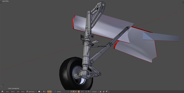
Step 6 - Fitting
I managed to collapse the entire MLG including rotation and so on without rigging it to see how and more importantly IF it fits. Needless to say it doesn't :)
However, it's not as bad as it looks. The nose gear fits just fine. On a more serious note, the glovebox has to be thickened a bit to the bottomside so the wheel fits. I don't plan on changing the general shape of the fuselage as it took 100s of hours to put it into this shape and it resembles RL 99.9% so any misalignment is down to the MLG and I don't plan on remodeling any part of the engine pods/lower fuselage. That being said the gear sits at a neat 90deg at the moment and in reality it tilts to almost 100deg and the wheel slightly inward to 95 so that will save some space.
Rigging this will be a bitch and shortcuts won't work, I realized that when I manually rotated the whole thing. In RL there is less than half an inch between the wheel and the forward inner landing gear door during retraction so that's gonna be interesting.
Apart from that it fits nicely in terms of length, width and wheel diameter:
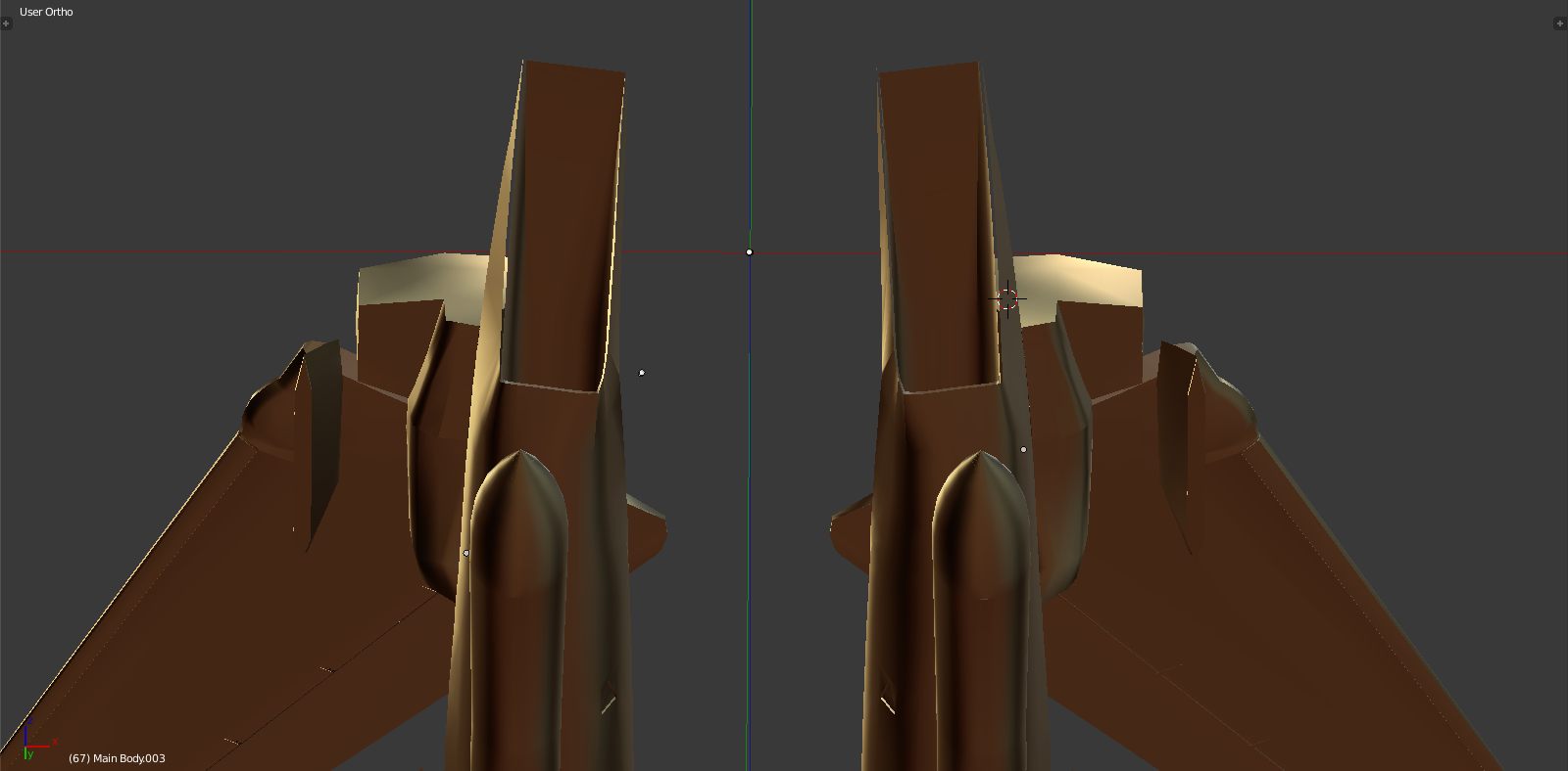
See how far the wheel cuts the engine pod line? That's why it literally rotates into the box during the last 10% of main strut rotation - insane design.
Lessons learned:
Even the Grumman blueprints are worth sh*t when it comes to MLG proportions and measurements.
Never model a landing gear in down position.
Whatever floats your boat, Baby.
Step 7 - Motivational Timeout
Anything you ever wanted or did not want to know about the Design Evolution that the Grumman F-14 Tomcat represented. Seriously, the best stuff you'll ever see on this jet presented by a former Grumman Engineer and Designer.
Step 8 - Corrections and more Corrections
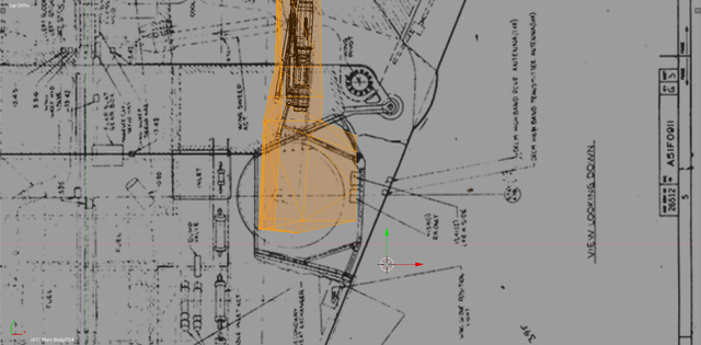
Originally I said: "Even the Grumman blueprints are worth sh*t when it comes to MLG proportions and measurements."
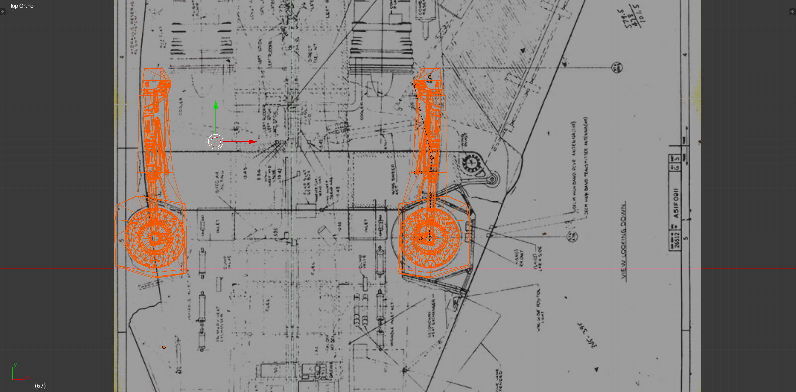
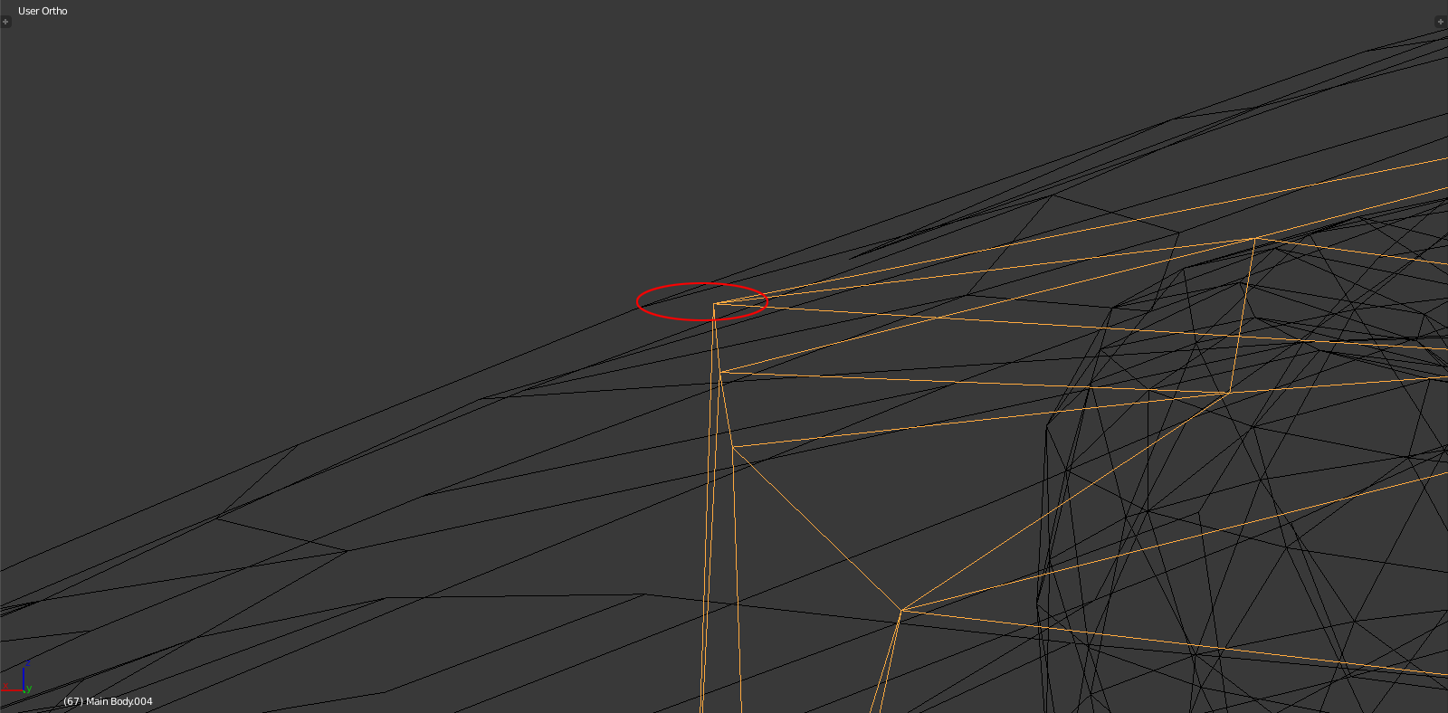
I retract that. While they are slightly inaccurate when it comes to the profile view in terms of angle and scale they are dead accurate when it comes to the 'wheelbox'. It took me ages to find the error here you see above. No matter how I tweaked the landing gear it just wouldn't fit in the bodyshell and constantly protrude through the landing gear doors...until now.
So what was the problem? This.
Basically the entire MLG sticks out of the fuselage. Move it up? Didn't work. Rescale? Can't cuz the scale is close 100% authentic (at least total length and diameter). Move it in? Can't cuz then it won't rotate freely. So what to do...
Here's another look:
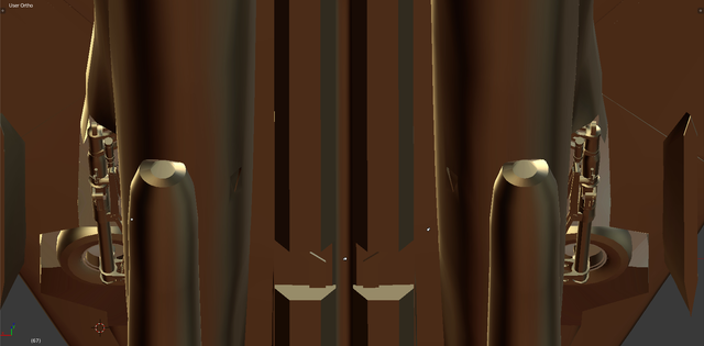
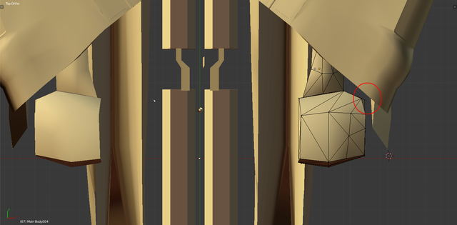
So the 'wheelbox' is too small, sits too far back and all in all just didn't fit. So I remodelled and repositioned the box. The entire gear was then tilted inward slightly as per the blueprint and the wheel strut extended out a good 50% more. Finally enlarged the wheel somewhat and fiddled with the hyfraulic lines and stuff on the MLG.
That looks better. Now need to check for clearance inward (engine pod/air intake), outward (landing gear doors), up (glovebox) and the upper inside rear edge cuz that is where the wings go when fully retracted. I tested this with full wing sweep and not oversweep but it should work. As you can see the margins are intensely small (like less than 10mm in some areas. Again the packaging is amazing on this design.
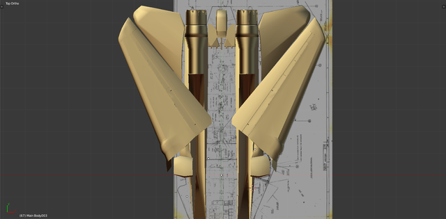
Wings:
As can be seen even in oversweep there is enough room.
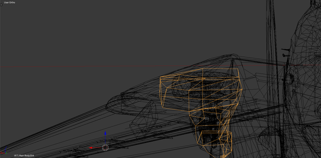
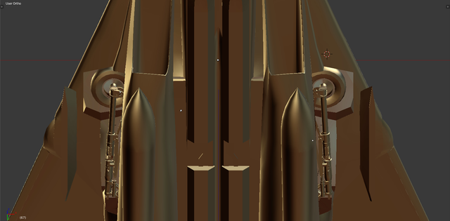
Glovebox:
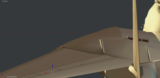
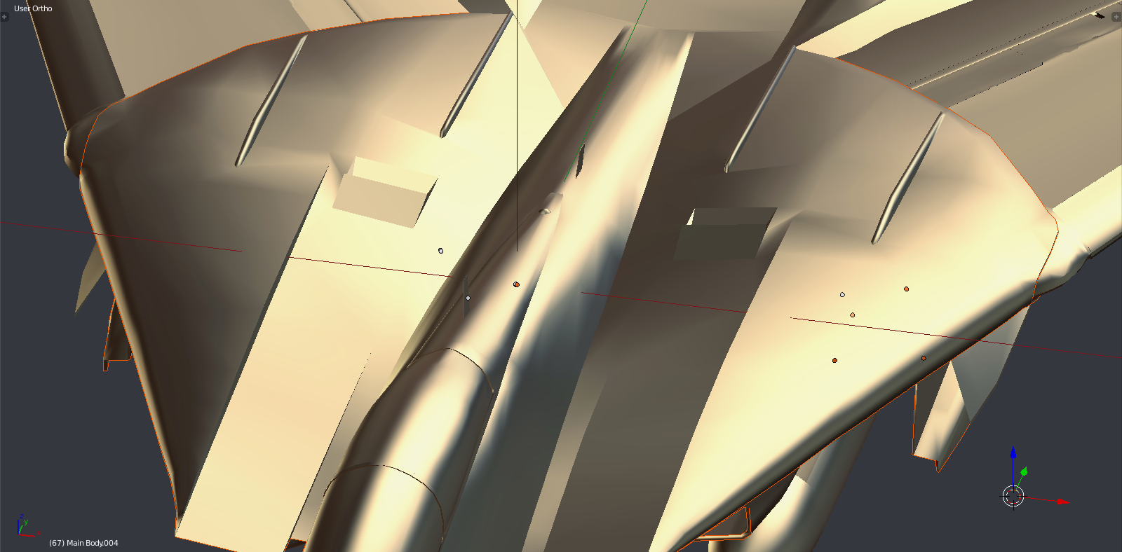
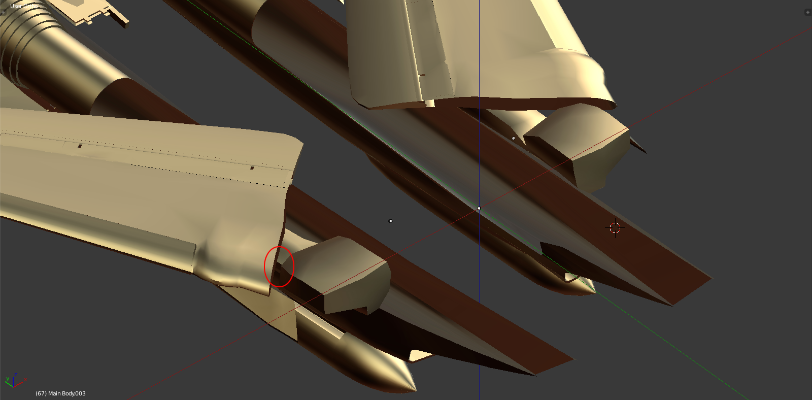
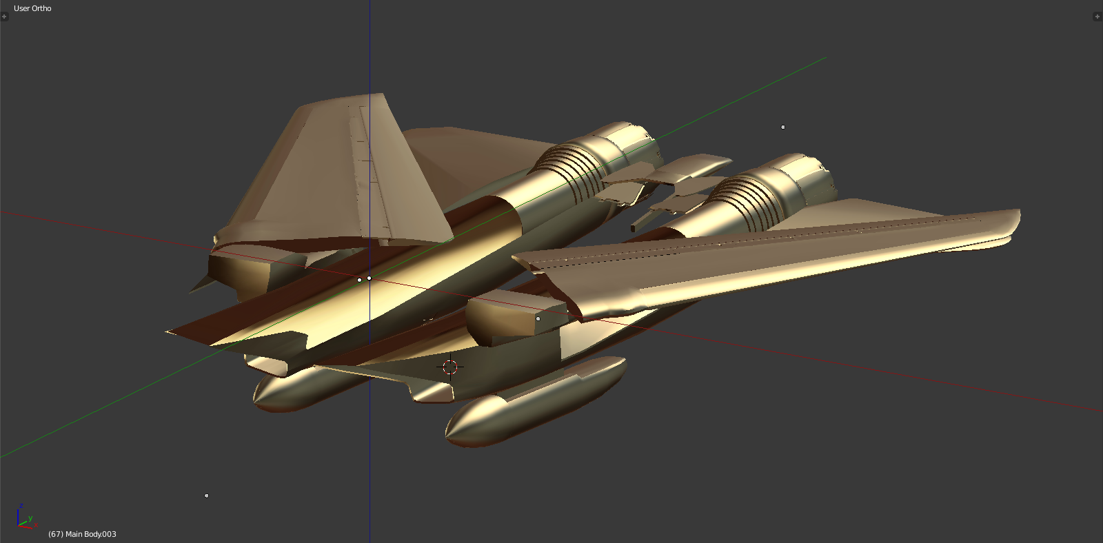
Enginepod:
That's gotta be one of my favorite shots of this model ever!
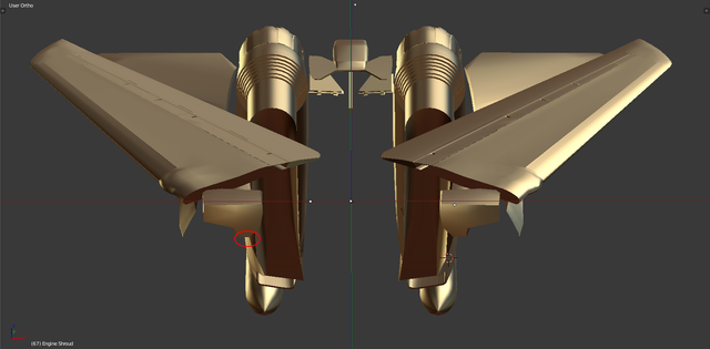
Now the weapon fairings:
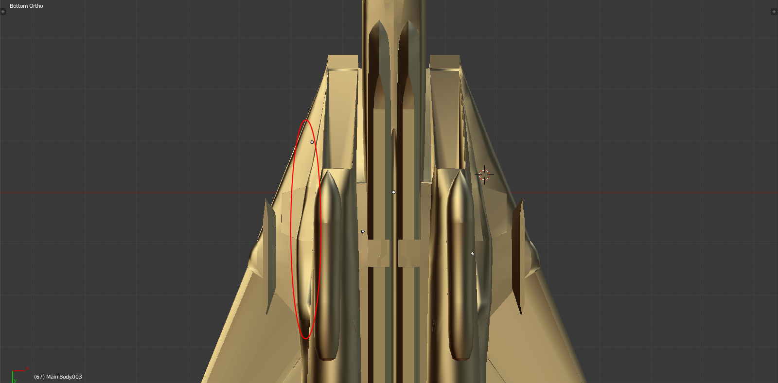
Also clear. Outlined is the 'waist section' of the fuselage housing the gear, this needs some fine tuning in the coming days now that it all fits together.
Some impressions:
Delta Tomcat, Baby.
Are your CAD drawings for the landing gear available for purchase?