Distributed wireless acoustic emission system and its application based on GPS/Wifi high-precision wireless synchronous clock
Distributed wireless acoustic emission system and its application based on GPS/Wifi high-precision wireless synchronous clock
2024-08-10 17:21
Jiehui Xie1) and Shifeng Liu3)
- QingCheng AE Institute (Guangzhou) Co., Ltd., Guangzhou, Guangdong, 510670, China.
Editor's Note: This report takes "Distributed Wireless Acoustic Emission System" as the research object, adopts two mainstream wireless synchronization methods, GPS and Wifi, and conducts research on high-precision wireless synchronization clocks. It has achieved satisfactory results in distributed acoustic emission positioning and data analysis of large-scale dot matrix arrangements, and is supplemented by field cases for specific explanations.
1 Fault location based on acoustic emission technology
One of the most important steps in the signal analysis of acoustic emission is positioning. The positioning function can directly know the location of the acoustic emission source, which is convenient for secondary inspection of the designated area. For example, the common positioning of the bottom of a storage tank may take several months if the traditional ultrasonic detection method is used, and the tank needs to be cleaned during the detection process. However, acoustic emission positioning does not require cleaning of the tank, and it only takes a few hours. If the test results show that further testing is necessary, ultrasonic testing is used. If there is no need for further testing, the test can be completed directly. Compared with the two, the acoustic emission method can reduce a lot of testing costs. In
order to realize the positioning function of acoustic emission, the time of each acoustic emission sensor collector needs to be synchronized, and the synchronization must reach the us level to achieve positioning in a smaller area.
2 Background of Traditional Time Synchronization
In desktop acoustic emission detectors before the Internet of Things era, inter-board transmission or wired transmission was widely used to achieve time synchronization.
2.1 Inter-board synchronization method
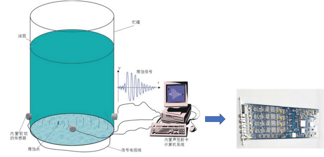
The figure below shows a company's acoustic emission tank bottom corrosion leakage detection system, which uses an inter-board transmission synchronization solution.
Acoustic Emission Tank Bottom Corrosion Leak Detection System
Figure 2-1 A company's acoustic emission tank bottom corrosion leakage detection system
This solution uses multiple acoustic emission sensors arranged around the tank body, and connected to the computer equipment with acoustic emission acquisition card through long-distance cables. By using an onboard high-speed bus with extremely high accuracy (up to 100 ns), the synchronous acquisition of multiple channels is controlled to achieve the positioning function.
The advantages of this method are:
- The synchronization accuracy is very high, which can reach the level of 100 ns;
- The sampling accuracy is high, which can reach 16~18 bits, and the sampling speed is high, 10Msps.
However, there are the following disadvantages: - The equipment installation is complicated;
- The cost is high;
- The integrated channels are limited, and it is difficult to achieve more than 100 channels;
- Affected by the length of the sensor line, the layout space is limited.
2.2 Wired synchronization method
The wired transmission method usually uses a serial interface as the transmission medium. Through the distributed chassis layout, the chassis transmits waveform parameters through wireless/wired networks (WIFI, 4G, LORAWAN, etc.), which can increase the layout space. The following figure shows a company's distributed acoustic emission detection system based on 485 bus.
Distributed Acoustic Emission Detection System Based on 485 Bus
Figure 2-2 A company's distributed acoustic emission detection system based on 485 bus
Schematic diagram of the distributed acoustic emission detection system
Figure 2-3 Schematic diagram of the distributed acoustic emission detection system
Each group of acoustic emission equipment contains N acoustic emission data acquisition channels (from 1 to N, dynamically configurable). The synchronization signal is transmitted through a high-precision bus within the equipment. The devices between the devices transmit synchronization information through the RS485 bus ring network connected by transceiver to achieve synchronization of the entire network. According to the load capacity of the RS485 bus, 30-40 groups of equipment can be connected, and the clock synchronization of the entire network can be achieved for a maximum of 700-800 channels.
This method has the following advantages:
- It can accommodate a large number of channels;
- Distributed installation can reduce the difficulty of installation;
- The layout space is large and the distance between devices can be very wide.
However, there are the following disadvantages: - The synchronization accuracy is general and can reach ten us level;
- When the 485 cable is long, a relay needs to be added;
- The installation is complicated, and there are many sensor cables and communication cables.
3 New time synchronization model in the era of the Internet of Things
Modern acoustic emission instruments have gradually entered the era of the Internet of Things. The previous method of using 485 industrial bus for wired time synchronization has the advantages of high accuracy, stable connection and high robustness, but it is not flexible and convenient in the application of large-scale acoustic emission wireless device clusters arranged in arrays. It is particularly important to choose a wireless and high-precision clock synchronization method.
Therefore, after repeated comparisons and experiments, we have determined the two mainstream wireless time synchronization methods based on GPS and Wifi, which have long controllable distances, stability and reliability. The specific design scheme is as follows:
3.1 GPS synchronization method
The GPS synchronization scheme of Qingcheng IOT acoustic emission equipment adopts a multi-mode satellite navigation synchronization method, supports Beidou III/GPS/GLONASS and other satellite positioning systems, supports multi-system joint positioning and single-system independent positioning, and realizes high-precision synchronization function.
Qingcheng IOT acoustic emission equipment receives the timing synchronization pulse of the GPS/Beidou module in space, uses a high-precision clock source (±1ppm) for timing, and refreshes the time by detecting the pulse edge of PPS, which can achieve a synchronization function of ±1us. In addition, by receiving the positioning information RMC message of Beidou III/GPS/GLONASS, the positioning function of the device can be realized.
Qingcheng IOT acoustic emission equipment adopts a miniaturized and integrated design. The equipment integrates sensors, acquisition circuits, rechargeable batteries and wireless synchronous communication function boards. It can realize wide-range acoustic emission signal acquisition, support networking of multiple wireless communication methods, support multi-channel combination synchronous network and other functions. It has the characteristics of small size, strong function and easy use.
Qingcheng IOT acoustic emission equipment based on GPS has the following advantages:
- It can accommodate a large number of channels;
- It is easy to install and only needs to be installed once;
- It is convenient to network and can realize communication with distance;
- It can realize long-term unattended operation;
- The layout space is wide and no cables are required;
- The synchronization accuracy is high, up to ±1us;
- Low cost.
There are disadvantages: - It needs to be placed outdoors and is greatly affected by GPS signals.
3.2 Wifi wireless synchronization method
The application of GPS and Beidou is ubiquitous, but the premise is to receive satellite signals. In closed plants such as dam plants, tunnel projects, and nuclear power plants where no signal can be received, synchronization can only be achieved by relying on time synchronization servers. In the field of monitoring, for convenience and safety reasons, some systems have to use wireless communication , especially for mobile inspection and monitoring systems, which can only achieve time synchronization and second pulse synchronization by wireless means.
3.2.1 WIFI wireless synchronization technology
WIFI wireless synchronization technology is controlled by the wireless master device in the WIFI network, and sends synchronization sequence beacons containing synchronization time identifiers and synchronization data packets to several wireless slave devices in the target device group in a wireless directional broadcast mode of a specific wireless mode. When a nearby wireless slave device receives the synchronization time identifier sent by the wireless master device, it establishes and maintains a synchronization matching state with the wireless master device according to the synchronization time identifier, and places the corresponding matching verification identifier in its device status beacon. In the synchronization matching state with the wireless master device, the wireless slave device maintains wireless time slot synchronization in each synchronization time period, and performs synchronization time correction at least once in each synchronization validity period to maintain the synchronization matching state. The wireless slave device starts receiving the synchronization data packet in its synchronization detection reception time slot, receives the synchronization data packet within the synchronization validity period, and places the status verification code of the current corresponding synchronization data packet reception into the device status beacon.
3.2.2 Qingcheng IOT sound emission device
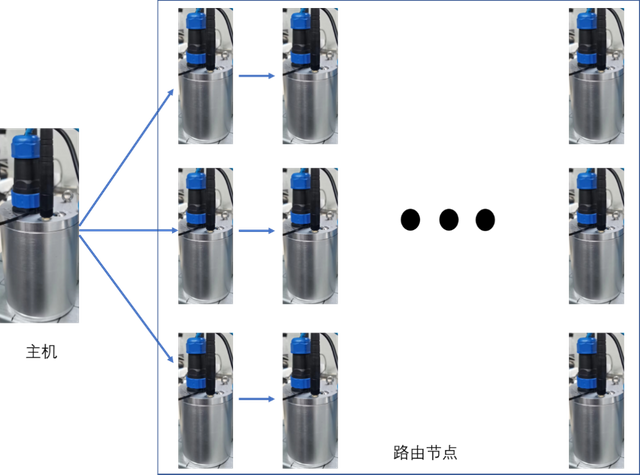
Qingcheng IOT sound emission device is based on the above wireless synchronization technology, uses the 2.4GHz ISM frequency band (the same frequency band as 2.4G WiFi, automatically avoids WiFi channels), and realizes the synchronization networking function through star network technology (1 host, the rest are routing nodes), as shown in the figure below.
Qingcheng IOT acoustic emission equipment system based on WIFI wireless synchronous networking
Figure 3-1 Qingcheng IOT acoustic emission equipment system based on WIFI wireless synchronous networking
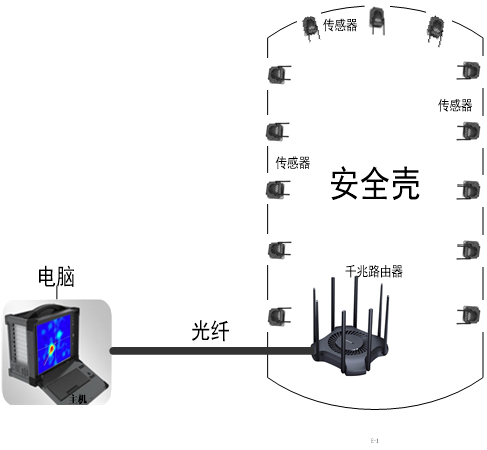
The following figure shows an acoustic emission detection system based on WIFI wireless synchronization used in a project. 100 devices are used to transmit data through a wireless WIFI router and a computer (analysis terminal). Time synchronization is performed through a wireless WIFI synchronization network to analyze the acoustic emission signal generated by the leak, thereby locating the fault.
Qingcheng IOT acoustic emission equipment based on GPS has the following advantages:
- It can accommodate a large number of channels;
- It is easy to install and only needs to be installed once;
- It is convenient to network and can realize distance communication;
- It can achieve long-term unattended operation;
- The layout space is wide and no cables are required;
- The synchronization accuracy is high, up to ±1us;
- The cost is low.
There are disadvantages: - It is greatly affected by the strength of the wireless signal and is easily affected by obstacles.
3.3 Summary
The above 4 synchronization methods have their own characteristics. When using them, you can choose the appropriate equipment according to your needs. The comparison of the 4 synchronization methods is as follows:
Table 1 Comparison of 4 synchronization methods
Signal accuracy
Installation Difficulty
Synchronization accuracy
Layout space
Maintenance Difficulty
cost
Inter-board synchronization
Highest
high
Highest
Small
high
Highest
Wired Sync
high
generally
middle
middle
middle
middle
GPS Sync
middle
Low
high
wide
Low
Low
Wireless Sync
middle
Low
high
wide
Low
Low
- 4 Overall design of wireless clock synchronization system
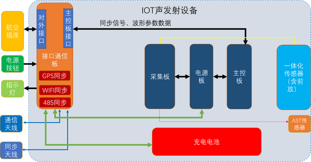
Large-scale equipment or systems in industrial production environments may experience unpredictable faults or anomalies during long-term operation. Acoustic emission equipment based on the Internet of Things can quickly detect the occurrence of faults or anomalies, and can be used for long-term real-time remote monitoring of large-scale equipment; based on high-precision acoustic emission source positioning, it can help engineers quickly locate the location of faults or anomalies, and can be used for structural reliability monitoring and detection of large-scale equipment. The environment in which large-scale equipment or systems are located is complex and diverse. Some are outdoor environments, some are indoor environments, and some are environments where wireless networks cannot be used. In order to adapt to the needs of various environments, the latest Qingcheng IOT acoustic emission equipment is internally compatible with three synchronization modes: GPS/wireless/wired. You can select GPS synchronization, wireless synchronization, and wired synchronization by configuring the synchronization mode. The device integrates GPS, WIFI synchronization, and 485 synchronization circuits. The switching of these synchronization function circuits is realized through the main control chip, thereby adapting to a variety of synchronization methods. The principle block diagram of the device is as follows:
Schematic diagram of the hardware principle of Qingcheng IOT acoustic emission equipment
Figure 3-3 Schematic diagram of the hardware principle of Qingcheng IOT acoustic emission equipment
In this way, the device can be compatible with a variety of indoor and outdoor, wired and wireless application scenarios, providing high-precision synchronization functions, thereby realizing the fault location function of the acoustic emission system.
The parameters of the device are shown in Table 2.
Table 2 Hardware parameters of Qingcheng IOT acoustic emission equipment
Channel combination
Multi-channel combination use
Input bandwidth
10KHz-1000KHz
Collection method
Signal trigger/time trigger
Analog Filters
Multiple frequency bands available
Synchronous clock
GPS: Synchronous clock better than 1us
WiFi: Synchronous clock better than 10us
Wired: Synchronous clock better than 10us
Protection level
IP62~IP67, can be configured according to user environment requirements
Collection frequency
Maximum sampling rate of single channel: 2M points/s
Built-in SD card capacity
64GB (expandable to 512GB)
Collection accuracy
16-bit
Communication
4G、WiFi、LAN等;
System noise
Better than 30dB
Operating temperature range
-20℃-60℃
AE characteristic parameters
Arrival time, amplitude, ring count, energy, rise time, duration, RMS, ASL
Data Output
Waveform, parameters, parameter rating, you can choose whether to upload waveform, parameters according to parameter rating
Digital Filter
256-order FIR filter, any value setting of pass-through, high-pass, low-pass, band-pass in the frequency range of 0KHz~1000KHz
powered by
12VDC external power supply, or built-in battery power supply, the battery working time is up to 40 hours.
4 Current Status of Wireless Synchronous Clock Equipment and Synchronous Clock Accuracy Test
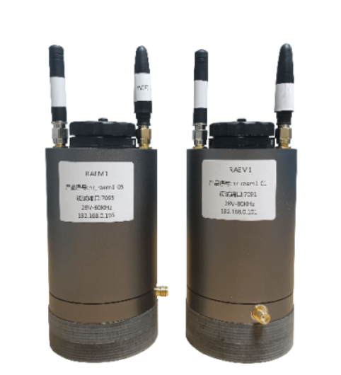
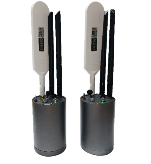
4.1 GPS /Wifi Wireless Synchronous Clock Version M1 Product Status
The GPS wireless synchronous clock version M1 acoustic emission detection system is a multi-channel real-time acoustic emission acquisition system that is transmitted from multiple independent single-channel acoustic emission collectors to the computer host software via WiFi or to the cloud platform via 4G. The data time synchronization between each collector is achieved by receiving GPS time, and the synchronization clock accuracy can reach within 1us, which is suitable for various occasions where time difference positioning is required, such as tank bottom corrosion time difference positioning, pressure vessel crack cracking positioning detection, etc. The
WiFi wireless synchronous clock version M1 acoustic emission detection system is a multi-channel real-time acoustic emission acquisition system that is transmitted from multiple independent single-channel acoustic emission collectors to the computer host software via WiFi. The synchronization networking function is realized through WiFi star network technology (1 host, the rest are routing nodes), and the wireless synchronization clock accuracy is better than ±10us. It is suitable for environments where synchronization can only be achieved by local networking in closed plants such as dam plants, tunnel projects, nuclear power plants, etc. where satellite signals cannot be received.
GPS Wireless Synchronous Clock Version M1
WiFi Wireless Synchronous Clock Version M1
4-1 GPS Wireless Synchronous Clock Version M1
4-2 WiFi Wireless Synchronous Clock Version M1
Table 2 GPS/WiFi Wireless Synchronous Clock Edition M1 Hardware Parameters
Channel combination
Single channel or multi-channel combination use
Input bandwidth
10KHz-1000KHz
Collection method
Signal trigger/time trigger
Analog Filters
Multiple frequency bands available
Wireless Synchronous Clock
GPS, synchronization clock is better than 1us
WiFi, synchronization clock is better than 10us
Protection level
IP62
Collection frequency
Maximum sampling rate of single channel: 2M points/s
Built-in SD card capacity
64GB (expandable to 512GB)
Collection accuracy
16-bit
Communication
4G、WiFi;
System noise
Better than 30dB
Operating temperature range
-20℃-60℃
AE characteristic parameters
Arrival time, amplitude, ring count, energy, rise time, duration, RMS, ASL
Data Output
Waveform, parameters, parameter rating, you can choose whether to upload waveform, parameters according to parameter rating
Digital Filter
256-order FIR filter, any value setting of pass-through, high-pass, low-pass, band-pass in the frequency range of 0KHz~1000KHz
powered by
12VDC external power supply, or built-in battery power supply
4.2 Synchronous clock accuracy test
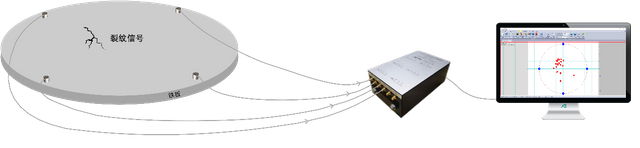
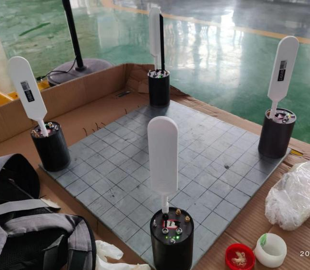
Take a 500mm×500mm steel plate, place the wireless synchronous clock RAEM1 on the four corners respectively, and break the 0.5mm HB hardness pencil lead along the path "A" on the iron plate to obtain the positioning diagram as shown in the right figure. The time difference accuracy is high and the positioning effect is good.
Test environment
Test Results
Figure 4-3: Test environment
Figure 4-4: Test results
5 Application solutions and cases
5.1 Accurate positioning of leakage in a nuclear power containment
When the leakage rate exceeds the standard during the overall sealing test of the containment of a nuclear power reactor building, the data is collected by the RAEM1 with high-precision wireless synchronous clock installed inside the containment and transmitted to the computer host software outside the containment, which can quickly and accurately find the location of the leakage point. The
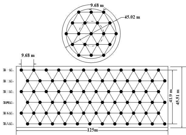
wireless sensor system consists of 100 wireless sensor units (1 host, 99 slaves) and computer host software. When a leak occurs, 100 RAEM1 with high synchronous clock accuracy simultaneously collect waveform data, and the time difference to the sensor in the array is calculated by the waveform correlation algorithm, and then the location of the leak source is calculated by the surface positioning algorithm. The structure and layout diagram of its wireless sensor system are shown in the figure below.
Sensor Block Diagram
Sensor Detailed Layout
Figure 5-1 Sensor principle block diagram
Figure 5-2 Detailed sensor layout
5.2 Pipeline Leakage Location
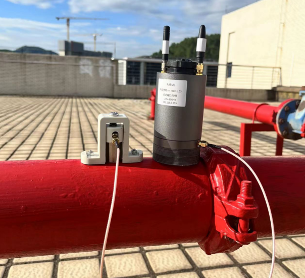
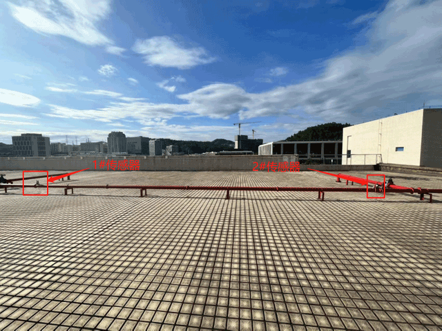
The sensor is installed on a 10-meter-long pipeline and connected to two GPS wireless synchronous clock versions RAEM1, as shown in Figures 5-3 and 5-4 below. The data is transmitted to the computer host software via WiFi.
Experiment 1: The lead is broken once in the middle of the two sensors, and the positioning diagram is shown in Figure 5-5;
Experiment 2: The lead is broken 6 times at a position 2 meters close to the 1# sensor, and the positioning diagram is shown in Figure 5-5;
Conclusion:
The GPS version of RAEM1 synchronous clock accuracy can accurately locate, and combined with relevant algorithms, it can be used for pressure pipeline external leakage or valve internal leakage.
Sensor installation diagram
Sensor distribution map
Figure 5-3 Sensor installation diagram
Figure 5-4 Distribution diagram of 1# and 2# sensors
Figure 5-5 Lead cut once in the middle
Figure 5-6 Lead breaks 6 times at 2 meters near sensor 1#
5.3 Atmospheric pressure tank bottom plate corrosion detection, spherical tank and other pressure vessel crack detection
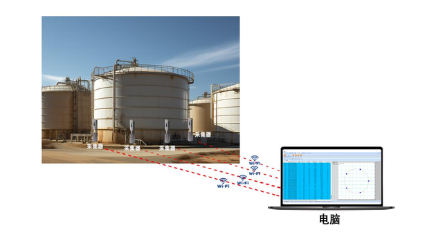
In traditional tank bottom plate corrosion detection, the sensor needs to be wired to the acoustic emission collector, and the cable needs to be pulled to power the acoustic emission collector. There are many cables, which is time-consuming and labor-intensive. The RAEM1 with WiFi wireless synchronous clock version has its sensor, collector, communication, clock synchronization, and battery integrated into the cylinder, which can completely eliminate wiring. The whole is powered by batteries and can work continuously for more than 5 hours, which fully meets the needs of 2-3 times of detection. The number of channels can be flexibly configured, which greatly improves the efficiency of detection. Its principle block diagram is shown in Figures 5-7 and 5-8 below:
WiFi wireless synchronous clock integrated version RAEM1 atmospheric pressure tank bottom corrosion detection
Figure 5-7 WiFi wireless synchronous clock integrated version RAEM1 atmospheric pressure tank bottom corrosion detection
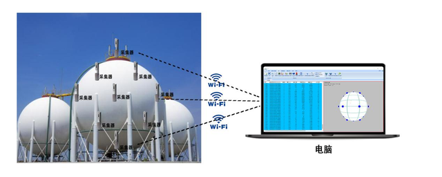
WiFi wireless synchronous clock integrated version RAEM1 spherical tank detection
Figure 5-8 WiFi wireless synchronous clock integrated version RAEM1 spherical tank detection
6 Conclusion
The distributed wireless acoustic emission system based on GPS/Wifi high-precision wireless synchronous clock can realize distributed high-precision wireless synchronous clock positioning. At present, it has been applied in the corrosion positioning of the bottom plate of atmospheric pressure storage tanks, crack positioning of pressure vessels, and leakage source positioning. With the Internet of Things acoustic emission equipment of the Internet of Things architecture, long-term online monitoring of wireless synchronous clock time difference positioning can be realized.