SLC S23 Week1 || Computer Repair - Power Supply
Assalam-o-Alaikum!
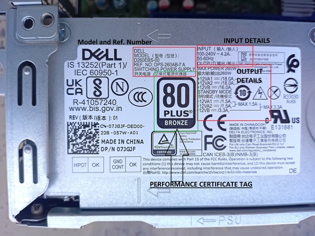
| ✅1. Examine the power supply unit of your computer or any other device and determine its type. Then, refer to the label on the unit to identify and note its input and output voltage specifications. |
|---|
Determination of the Type of Power Supply
Features
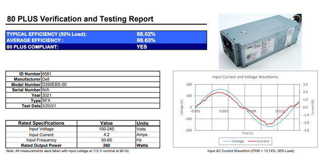
- SFX stands for Small Form Factor, which means that these power supplies have been designed for a particular fit physical state for small case computers like Optiplex 5000 that I am currently using to work on.
- This power supply has dimensions of 62mm x 82mm x 185mm.
- It has 80 PLUS Bronze, which means 82% efficiency at 20% load, 85% efficiency at 50% load, 82% efficiency at 100% load.
- Comparison with ATX Power Supply
- There is a significant difference between SFX and ATX. SFX are more compact than ATX Power Supplies (Power Supply).
- They have small quiet fan.
- They have smaller caples. (Probably limiting extra connections in Computer Device) but have footprints in them.
- They are specially designed for small case computers or devices but give the same power and efficiency as Powerful ATX Supplies give.
- SFX PSU is more expensive than ATX PSU. (In the market of my city)
- Input Specifications
- Explanations
- Wide Ranging Potential Difference 100-240V
- Wide Ranging Elecrtical Frequency 50-60Hz
- This device can work on both 50 & 60 Hertz of an electrical vibration. Moving away from the depth of the frequencies model, most of the European countries electrical supply companies provide electricity of 60Hz frequency whereas, in Asia, electrical companies provide 50 Hz electrical frequency (i.e., Pakistan). This device can work well on both frequencies.
- Maximum Current Flow 4.2 Amp.
- This indicates that it can allow the flow of current from its circuits of 4.2 Amp., which is a good amount of current,t without damaging its circuits.
- Output Specifications as Max. Output
- Rails are the pathways that deliver power to different components of a device. They help to distribute the power to the components according to their need and requirements. A rail of +12V is important to provide power to the high functioning components like CPU or GPU. The above table indicates the function of +12VA1 & 12VA rails to turn on the functions of a CPU & GPU. The rail 12VB indicates the function of the motherboard and drivers (covering all smaller components).
- These rails have the advantage of preventing overloading,g and they enhance the safety measures in a power supply unit. However, the power supply may be a multi-rail power supply unit or a single-rail power supply unit. Both have their pros and cons. A single rail has no power distribution limitation. But, any short circuit may damage the whole system. Where multi-rails PSUs are safer, but if the required component like GPU needs 30A, the limited rail will hardly run that component.
- Output Specifications as Standby Output
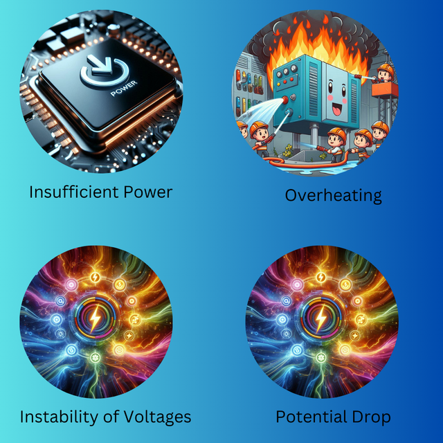
- Insufficient Power provided by the PSU is not enough for the system.
- Components or the PSU itself is overheating due to high load or due to failure of thermal protection system failure.
- Instability in the voltages provided by the PSU to the motherboard.
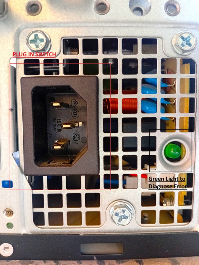
- It also indicates electrical issues like sudden drops in the voltages from external electrical sources (like as main power switch) leading to sudden shutting down of the PSU.
- Diagnosis
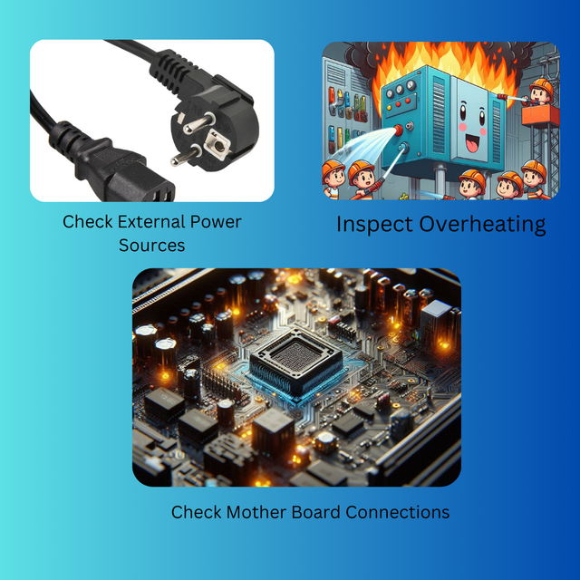
- Check External Power Sources
- Bypass PS-ON & GND
- Check Motherboard power connections
- Reasons
- Diagnosis
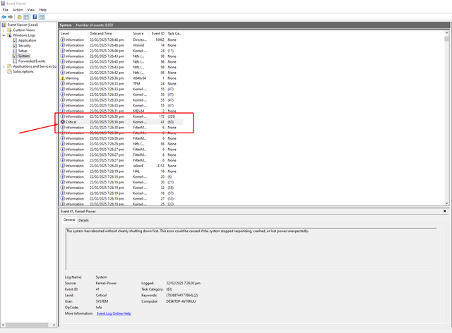
- Inspection through Windows
- Inspection through BIOS
- BIOS we all know Basic Input/Output System. It is used to start the computer after powering on until it meets Windows. In a DELL system press the F2 key to get the BIOS page and then navigate to Hardware monitoring or PC Health check. When press, note the following readings:
+12V Rail: Acceptable range is 11.4V to 12.6V.
+5V Rail: Acceptable range is 4.75V to 5.25V.
+3.3V Rail: Acceptable range is 3.14V to 3.46V.
If the voltage range falls outside this, then there is a PSU failure. (These readings are specific only for Optiplex 5000)
Source
Overheating or Burning of Components
- Overheating is common but burning is most crucial because timely actions can destroy the whole computer setup.
- Reasons
- The major reasons include a heavy load on the computer PSU more than its capacity, a fault in the cooling system, and short circuits in the computer. Sometimes, many GPUs and CPUs require power more than the power supply provides. If the PSU does not meet the power requirement, then overloading on the PSU happens. In such cases, if the high safety measures are present in the system, then it shuts down but if it is not, then the overheating and the burning of components occurs. Failure of the cooling system, especially failure of the cooling fan causes the components to overheat and burn. Similarly, short circuits also lead to the same problem.
- Diagnosis
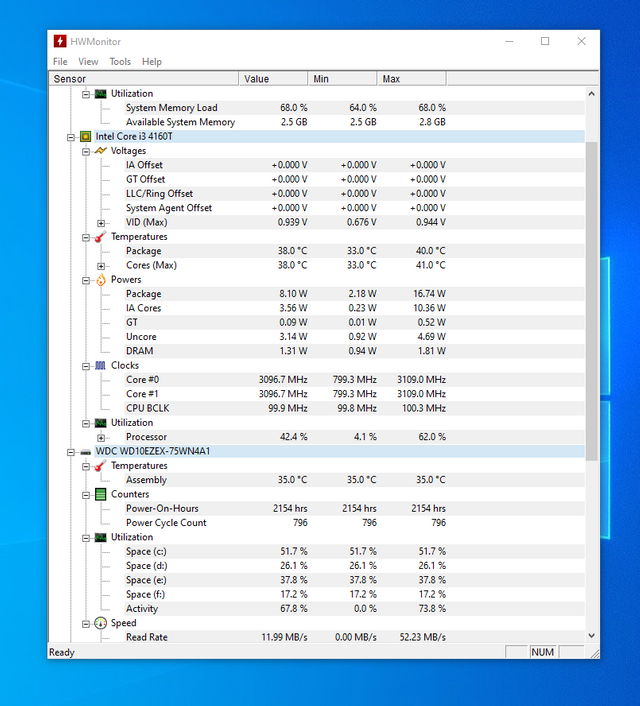
- Using HWMONITORING Software
- The first diagnosis is to check the temperature through the HWMONITORING software. I installed it multiple times to check my PSU condition. The suggestions given by the software are here:
CPU: Idle (30-50°C), Load (60-85°C), Critical (>90°C).
GPU: Idle (30-50°C), Load (60-85°C), Critical (>90°C).
- Check Cooling System
- A cooling system includes a fan and thermal paste in a common computer but high-end computers have a water or crystal cooling system which is more effective. Relying on the general cooling system, inspect the fan working and thermal-paste or heat sink cages. If there is any heating issue with them then immediately remove them and recover them.
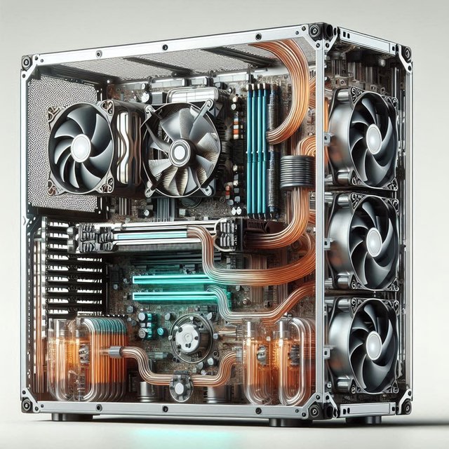
Representational Graph Generated and Edited on Canva
Un-usual noises in the Computer System
- As it has been explained the PSU is responsible for providing power to all components of a computer. It is responsible for all underlying components working. But if it starts to give unusual sounds of clicking, buzzing, or in rare cases sparking, then there could be several problems with underlying components leading to the failure of the system.
- Diagnosis through noise
- Trough Scraping Noise
- Trough Click-Sound
- Trough Buzzing
- Protection from Electrical Shock
First of all, it saves the mechanic from an electrical shock. Usually, a powerful power supply has potential up to 300V. This high potential difference is enough to allow high amperes of current to flow from it. If the connection is not cut, then it can cause serious hazards for the observer, clean,r, or mechanic. Therefore, Powering off the PSU not only prevents the electrical shock but also provides a free environment for a mechanic to touch it fearlessly. - Prevents Short Circuits
There is a large number of such cases in the world when people face an electrical shock due to short circuits of electronic devices. In particular, mechanics are mostly affected by it. The science behind this fact is; that they use metallic equipment to touch and open these devices and due to some wrong touch, the device faces short circuits. Therefore, powering off also helps as a safety measure. - Prevention of Fire Hazard
If I exaggerate this matter, powering off may also prevent fire hazards. Especially when the PSU is out of order and is judged for the recovery. Overheating PSU diagnosis requires high stress for Powering off the PSU before inspecting. Avoid Using Liquids
Liquids are mobile and the presence of ions enhances their character to carry the electrical current as explained in chemistry books. Therefore, they must be avoided use not only for PSU but also for any other sensitive electronic components.Use Soft Brushes for Cleaning
PSU and other computer components are very sensitive to break. Therefore, they need smooth and careful cleaning. For this purpose, to clean dust from fans a soft and smooth brush must be used.Use Air to clean Dust
Using air to clear dust is beneficiary to keep the components safe from circuit breakage and gives a smoother cleaning to the components. Therefore, vacuumed air should be used to clean the components from dust.Form Strong Connections
Loose connections may cause power cut-offs and short circuits. Therefore, for best maintenance, strong bonding of connection is a major step.Examin Cooling System of PSU (Fan or Heatsink)
Good maintenance requires regular inspection of the fan and in high-end power supplies the heatsink cases additionally. The fan is a major cooling system, therefore its cleaning and dusting should be done regularly using a brush or vacuum pump.Monitor Temperature
Temperature monitoring inspection means the inspection of the cooling system. But, some drives like HDD or SSD do ave not have a separate cooling system, and therefore, their temperature must be inspected using software like HWMONITIORING, etc.Control Humidity
I have faced this issue a lot of times whenever I was a user of i3. But, still, when the computer is placed in a humid place, it catches it and starts restarting various components one after one. Therefore, a balanced environment is necessary to prevent humidity from the PSU.Replacing of Old Problematic Power Supply Unit
If PSU is five or six years old and causes any problem randomly, it must be replaced to maintain the life of the whole computer system. In my point of view, we should keep on changing our components, especially PSU after a certain long period of use even if they are not giving any obvious problems. This is an effective step for the extension of the life of all components.
Input & Output Voltage Specifications
| Specifications | Values | Units |
|---|---|---|
| Input Voltage | 100-240 | Volts |
| Input Frequency | 50-60 | Hertz |
| Input Current | 4.2 | Amp. |
During my study of the Power Supply, multiple questions about its range and limitations came to mind. For example, why is the potential difference so wide, ranging from 100 to 240 Volts? The answer is given in the description below.
- The Potential Difference of this Power Supply is ranging from 100-240V. This indicates the universality of this power supply that can work at various geographical locations where different values of Potential Differece are provided. Like USA provides the Potential Difference of probably 110 Volts. Similarly, in Pakistan, the 220-240 Volts Potential Difference provided; this device can work well at multiple locations.
| Voltages through Rails | Current Distribution |
|---|---|
| +12VA1 | 18.0 A |
| +12VA2 | 18.0A |
| +12VB | 16.0A |
| Total Output Power | 260 Watts. |
Concept of Rails
| Voltages through Rails | Current Distribution |
|---|---|
| +12VA1 | 1.5 A |
| +12VA2 | 1.5A |
| +12VB | 3.3A |
| ✅2.ATX power supplies supply power to ATX cards through a 24-pin connector. List the wire colors used for each number in the following table. |
|---|
| Sr.# | Potential | Color | Emoji | Sr.# | Potential | Color | Emoji |
|---|---|---|---|---|---|---|---|
| 1. | +3.3V | Orange | 🟧 | 13. | +3.3V | Orange | 🟧 |
| 2. | +3.3V | Orange | 🟧 | 14. | -12V | Blue | 🟦 |
| 3. | GND | Black | ⬛ | 15. | GND | Black | ⬛ |
| 4. | +5V | Red | 🟥 | 16. | PS-ON | Green | 🟩 |
| 5. | GND | Black | ⬛ | 17. | GND | Black | ⬛ |
| 6. | +5V | Red | 🟥 | 18. | GND | Black | ⬛ |
| 7. | GND | Black | ⬛ | 19. | GND | Black | ⬛ |
| 8. | PW-OK | Gray | 🌚 | 20. | -5V | White | ⬜ |
| 9 | +5VSB | Purple | 🟪 | 21. | +5V | Red | 🟥 |
| 10. | +12V | Yellow | 🟨 | 22. | +5V | Red | 🟥 |
| 11. | +12V | Yellow | 🟨 | 23. | +5V | Red | 🟥 |
| 12. | +3.3V | Orange | 🟧 | 24. | GND | Black | ⬛ |
| Color | Potential/Volteges | ||||||||||||||||||||||||||||||||||||
|---|---|---|---|---|---|---|---|---|---|---|---|---|---|---|---|---|---|---|---|---|---|---|---|---|---|---|---|---|---|---|---|---|---|---|---|---|---|
 +3.3V | This wire is used to carry low voltage functions like RAM (Random Access Memory) and PCIe (peripheral component interconnect express). In fact, in some systems, some parts of BIOS and CMOS use +3.3V potential. Overall, this wire is used for all such components that require voltages less than +5V and +12V rails.  +5V | This wire provides power to all such components that require voltages more than +3V but less than +12V of potential. USB ports, logic circuits, low storage devices such as SSD(low value or external), and standard USB port equipment like keyboards, mouse, microphones, and cameras are provided voltages using this wire. It was an important part of old computers as well, but modern computers also have significant importance for this rail. Many components that require voltages more than +5V work properly on +12V along with +5V.  +12V | +12V rail is one of the most important rails in a computer system because it provides potential to the most powerful components like CPU (Central Processing Unit), GPU (Graphics Processing Unit), high-performance SSDs (enterprise grade) that require high load for performance. An interesting fact that I know is that it is the most power-hungry wire/cable and is the most important part of modern computer systems. It is manufactured in yellow color to ensure its safety and caution about having high voltages among all wires. As the yellow color indicates caution ⚠️.  GND (Ground) | Well, when I read about this one in the contest post, I started to think about the meaning of the word GND. What does it mean? Why is it called GND? What is its function? After reading the PDF guidebook and searching from some internet sources, I knew GND stands for Ground wire, and it is considered to be the most essential circuit component because of its preventive ability. It has no voltages, but what it has is the preventive ability. It completes the whole circuit and provides a path for voltages. Every rail of +3.3V, +5V, and +12V needs a return path to complete its circuit. It also helps to reduce the electrical noise and the interference produced during the electrical flow in the whole circuit. Overall, it helps to balance voltages and also acts as a neutral wire (wire not designed to designate voltages), but the wire is of great importance in modern circuits.  +5VSB (Standby) | Standby mode is a condition in which the device turns off its maximum functions but remains switched on. The best example is to put the computer in sleep mode. In such conditions, the device uses very low voltages but remains switched on. Purple wire in the devices fills this need.  PS-ON | The green wire is used to turn the power supply on or off, which means that it gives the power supply to instruct the processing. According to my information, when GND gets its connection with PS-ON, the power supply turns on and provides voltages for all components to work and vice versa. The PSU can be turned on without the motherboard just connecting PS-ON with GND (with the help of wire).  PW-OK | This gray color wire ensures whether the Power Supply Unit (PSU) is working properly or not. This uses a very simple technique use, and that is when all components are working properly, then this wire sends +5V to the motherboard,d which ensures the working of all the components properly. But, when any fault hits the PSU, this wire drops the voltages to 0V, which makes the PSU switch off or restart.  -12V | I loved this one concept during the research for all blogs. This enhanced my understanding of the concepts that I did not understand in college. -12V typically indicates that 12 times less than zero. Here was the matter of confusion. I thought about how the voltages can be 12 times less than zero or non-existing voltages. But, after taking a review and remembering the college concepts of electrostatic, I understood the concept of voltages. Voltages do not exist, they are just studies or assumed comparatively between two bodies. -12V stands for 12 volts less than the ground, and at ground, the value of voltages is zero. But taking the +12V as the peak of a mountain, 0V as the sea level, and -12V as the depth of the sea, I easily assumed the concept of voltages when they have a negative sign. I hope all the visitors will understand. Well, moving to the functions of this wire, olden PCs have a vast diversity in their use, but the modern models of DELL company especially do not use it. On my computer too,o which is Optiplex 5000. Early sound and network are needed, and they provide the potential of very, very low quantity. This rail or wire provides -12V relative to the ground. Its use has been taboo in modern motherboards.  -5V | Similarly, like the previous one, this rail provides the potential of -5V compared to the ground. It was also used by the old architects, but in the modern PSU, its use is not observed. After introducing the ATX 1.3, this wire was completely removed due to its unneccessity. In the above table, I noticed the presence of +3.3V potential wire about four times. A question was raised in my mind that wasn't only one enough to fill the space for +3.3V potential work. Then I searched from different sources and collected some formal information and understanding, and I yielded from my search that multiple wires of +3.3V provide a smoother and easier way to flow the current from them.
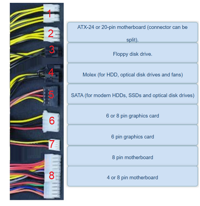
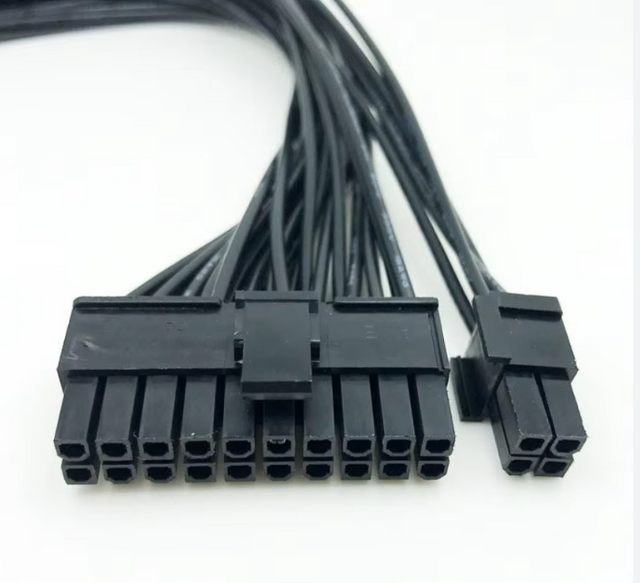
1. 4 or 8 Pin Motherboard ConnectorThis is known as EPS12V connector. This name comes from its capability to carry +12V potential as it has two yellow cables indicating +12V capacity of carrying voltages. It is a high-power cable in EPS systems. It is mainly used to run CPU, and therefore, it has high power. This cable is available in 4+4 pins or a single 8-pin pot. According to my information, it is called EPS12V with 8-pins. It is found in heavy-duty overclocking systems (those that can work for hours,) like the most updated systems of Intel Xeon or AMD. I use Optiplex 5000, Core TM i7computer considered to be a high-end PC, but this cable is not found in that.
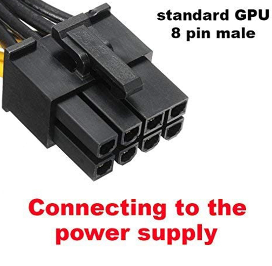
2. 8-pin Motherboard ConnectorThis provides additional power to the CPU and is found in all the high-end computers that can overclock. This is also called EPS12V. It is used on gaming and workstation computers. It is also not available in my Optiplex 5000. This may provide up to 300W power to the computer, making it heavy-duty. It has four yellow and 4 ground (black) cables. Each yellow cable is +12V cable,e and combined, ed it makes a powerful connector to EPS12V. Each yellow wire can handle up to 8A current. Whereas four black cables means four return paths which lower impedance and let the run current smoothly.
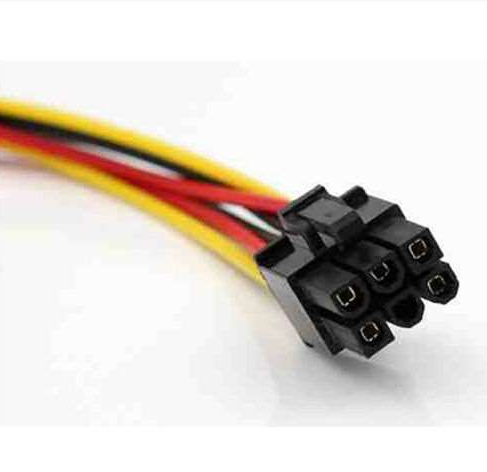
3. 6-pin graphic cardAlmost all computers that support GPUs have PCle (Peripheral Component Interconnect Express) slots, but sometimes, when a user uses any high-performance GPU, the power provided by the PCIe slot becomes insufficient, and therefore, there is always a need another power supply to that GPU and this deficiency is filled by installing an extra cable which is known and 6-pin GPU connector. A 6-pin connector can provide power up to 75W, and collectively, ly a GPU with slot and cable can gain power up to 150W. This 6-pin GPU connector is used in mid-end computers. It has the yellow each of +12V potential and three black (GND) cab,les which form a stable circuit flow in the whole loop.
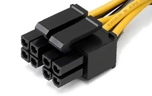
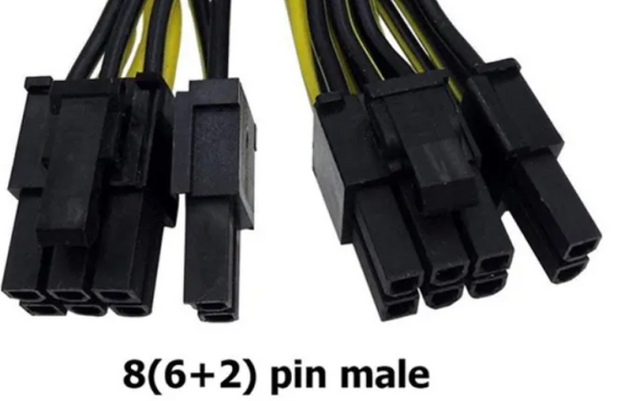
4. 6 or 8-pin Graphic CardThis cable offers the flexibility of whether 8 or 6 slots could be used. It has the same functions as the previous one, but it provides higher power to the GPU. It provides 75W power when 6sixpins are used but provides 150W when all eight pins are connected. This is used in mid to high-end computers. In mid-end computers, six pins are used, and in high-end computers, all eight pins are used. Collectively in a high-end PC, it provides the power of up to 225W along with PCIe slot.
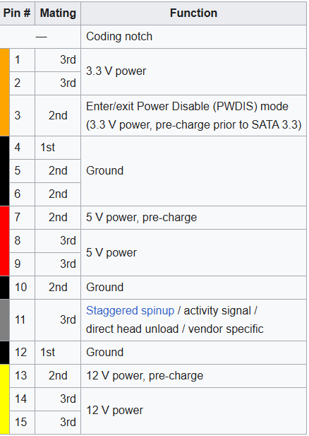
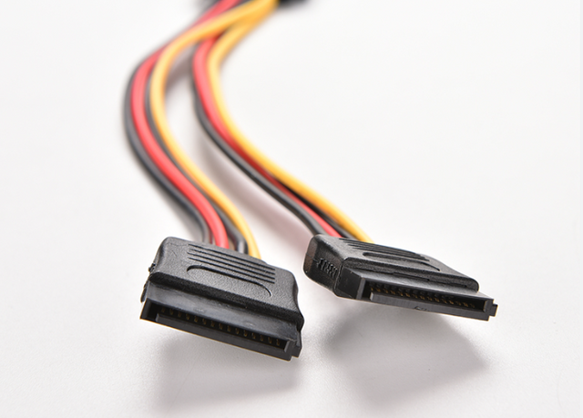
5. SATA (For modern HDDs, SSDs & Optical Disk Drive)SATA cable is used to transfer power to HDDs, SDDc, and other components. It has 15 pins, and there is a significant sequence in them. SATA has three types of power,r, which are +3.3V, +5V, and +12V. Each of these power sources has three pins in parallel to reduce impedance, which provides a better ground for the system. There are three pins in the first sequence of 3.3V and then three grounds, then three pins of 5V and then three grounds, and again three grounds and three pins. I studied it from WIKIPEDIA, and therefore, a graph from Wikipedia source is here. We can ask that SATA power is a modern power form because it provides a better experience for the components and starts a stable connection in a computer system.
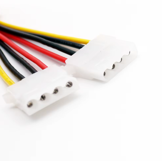
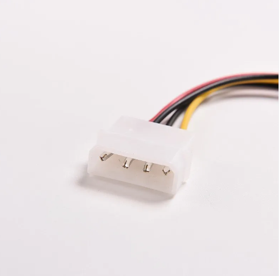
6. MolexMolex is as used as SATA, but it has only four-pin connectors, limiting it to the +5V and +12V potentials. Yellow wire is 12V, while Red wire is 5V, and they are present at the sides. Inner black wires are ground wires that provide the complete loop to the current flow and reduce the risk of short circuits, providing stability to the system. It was widely used in computers up to 200,3, but the SATA c, le which is a modern form of this cle, is now a says is widely used.
7. Floppy Disc Driver CableThis is known as floppy disc drive cable and this cable was very common in 1990-2000 AD. It is a four-pin connector having one Yellow, One Red and two black cables of +12V, +5V and GND respectively. An interesting thing about this cable is that, it is an old cable but considerably earlier cable to work on locking mechanicsm. According to my studies, the locking mechanism provides connection security and prevents accidental disconnection, loss of connection, and incomplete bonding with the component. Modern cables described earlier use a locking mechanism too but this is the earlier one in personal computers to use it. Nowadays, these cables have been outdated.
8. 24 or 20-pin ATX motherboard connector.This is considered to be one of the most important components that supply power to the main motherboard to function primarily. It could be seen in any computer PSU but the computer I am using is void of this power cable. I am currently using Optiplex 5000 and it has SFX power supply unit and has been designed to Small Form Factor which means for a specific space as described in the answer to question 1. But, its functions are already described in detail in question number 2. Additionally, I can tell that it also ensures safe booting, provides power in standby mode, and ensures primary power to the motherboard, along with a secure connection it has a backup capability due to its 24, and 20-pins, older PCs can also use it.
Occurance of Random Shutdown and restart of PSUThis is one of the most common signs of a failing PSU in computers it starts to turn off automatically and begins to start. This only happens when becomes very much to the whole system and instability of voltages occurs in computers. This leads to sudden loss of power for PSU and it turns off or restarts automatically.
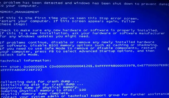
BSOD (Blue Screen of Death)
There are commonly three types of noises that can be heard from computer PSUs.
Precautionsi) Power off & Unplug the connectionThis is an obvious step to take before touching and cleaning any electronic equipment, not only the power supplies. This is done to further the multiple precautions that this action provides. ii) Let the Capacitor DischargeIn the previous precaution, I did not discuss Unplugging importance anywhere. It has all to do in this section. Many power supplies can store some amount of charge in them as a residual charge. Many electronic devices like computers and TVs still power when they are turned off from the remote. Here, the capacitor plays an important role. But, when the PSU has been discharged, it must have nothing to do with the power connection, and literally, the capacitor will release its all charge making the PSU neutral. iii) Work in Anti-Static EnvironmentThis is a small step but sometimes proves crucial while inspecting the electronic devices. Let's understand it with an example. Nowadays, it is winter, and many of us have experienced an electrical shock just touching any metallic pot or even touching any other human. This happens only when a person stores an electrostatic charge in his body When he touches metals especially, he feels a strong jerk coming from electrical shock. This is a shock due to electrostatic charge flow. I studied it in my college and this step must be taken before dealing with electronic components. Mechanics must rubber gloves or shoes to prevent it.
Best Cleaning Practice
Best Maintenance Practice |
.png)
.png)
.png)